Light source heat-dissipation structure of backlight module

a technology of heat dissipation structure and backlight module, which is applied in the direction of illuminated signs, display means, instruments, etc., can solve the problems of high temperature of light-emitting diodes in the package structure, the inability to timely dissipate, and the inability to emit light by itself, so as to reduce production costs, reduce heat dissipation efficiency and the lifetime of light-source structures. , the effect of relatively enhanced heat dissip

Inactive Publication Date: 2012-10-04
TCL CHINA STAR OPTOELECTRONICS TECH CO LTD
View PDF15 Cites 2 Cited by
  • Summary
  • Abstract
  • Description
  • Claims
  • Application Information

AI Technical Summary

Benefits of technology

[0009]The present invention is to provide a light source heat-dissipation structure of a backlight module, which comprise at least one light-source structure, a heat-dissipation base and a carrier, wherein the heat-dissipation base directly supports and thermally contacts the light-source structure. Thus, it is helpful for the light-source structure to directly conduct heat and dissipate heat in accordance by good properties of thermal conductivity and heat-dissipation of the heat-dissipation base, so that the heat-dissipation efficiency and the lifetime of the light-source structure can be relatively enhanced
[0010]The present invention is to provide a light source heat-dissipation structure of a backlight module, wherein the light-source structure, the heat-dissipation base and the carrier are combined with each other in turn, so that the carrier will not be directly affected by the heat energy which comes from the light-source structure. Hence, the lifetime of the carrier can be relatively enhanced.
[0011]The present invention is to provide a light source heat-dissipation structure of a backlight module, wherein the light-source structure, the heat-dissipation base, and the carrier are combined with each other in turn, and fillers which are filled in through holes of the heat-dissipation base and the carrier not only electrically isolate leads of the light-source structure from the heat-dissipation base, but also the fillers may help the heat-dissipation base is firmly combined with the carrier. Thus, it is unnecessary to use thermal conductive adhesives between the heat-dissipation base and the carrier, so as to lower the production cost and the whole thickness for carrying out the purpose of compacting products.

Problems solved by technology

However, the liquid crystal material of the liquid crystal display cannot emit light by itself, and must depend upon an external light source.
But, the disadvantage of the light source heat-dissipation structure is that a temperature of a light-emitting diode chip of the light-emitting diode package structure during working is very high, and the light-emitting diode package structure just can indirectly conduct heat energy to the aluminum heat-dissipation base through the circuit board though.
Because of materials of the printed circuit board have high thermal resistance, the aluminum heat-dissipation base of the backlight module cannot timely dissipate the heat energy which comes from the light-emitting diode package structure.
Thus, the temperature of the surroundings of the light-emitting diode package structure will obviously raise and cause uneven temperature distribution in each of display blocks of the liquid crystal display and a reddish phenomenon due to the high temperature, resulting in affecting the imaging quality of the liquid crystal display.
Moreover, the light-emitting diode is very easy influenced in a luminous efficiency and stability because of the increasing temperature thereof during working, and a serious consequence may lower the lifetime of the light-emitting diode due to the long-term high temperature situation.
Besides, if the light-emitting diode package structure is just simply attached on the aluminum heat-dissipation base by an adhesives or fixed on the aluminum heat-dissipation base by screws, the efficiency of the conducting heat will be influenced to a certain extent due to indirectly thermal contact between the circuit board of the light bar and the aluminum heat-dissipation base, insulating adhesives existing therebetween, or un-tightly surface attachment therebetween, and the thickness of whole structure will also be increased and thus not helpful to the design trend of compactness.
In addition, under the long-term high temperature situation, the adhesives may deteriorate and lose viscosity, so that the light bar will depart from the aluminum heat-dissipation base.
If the heat of the light-emitting diode package structure can not be timely dissipated by the fixed plate, there will be a potential risk in overheat damage of the light-emitting diode package structure.

Method used


Image

  • Light source heat-dissipation structure of backlight module
  • Light source heat-dissipation structure of backlight module
  • Light source heat-dissipation structure of backlight module

Examples


Embodiment Construction

[0026]The foregoing objects, features and advantages adopted by the present invention can be best understood by referring to the following detailed description of the preferred embodiments and the accompanying drawings. Furthermore, the directional terms described in the present invention, such as upper, lower, front, rear, left, right, inner, outer, side and etc., are only directions referring to the accompanying drawings, so that the used directional terms are used to describe and understand the present invention, but the present invention is not limited thereto.

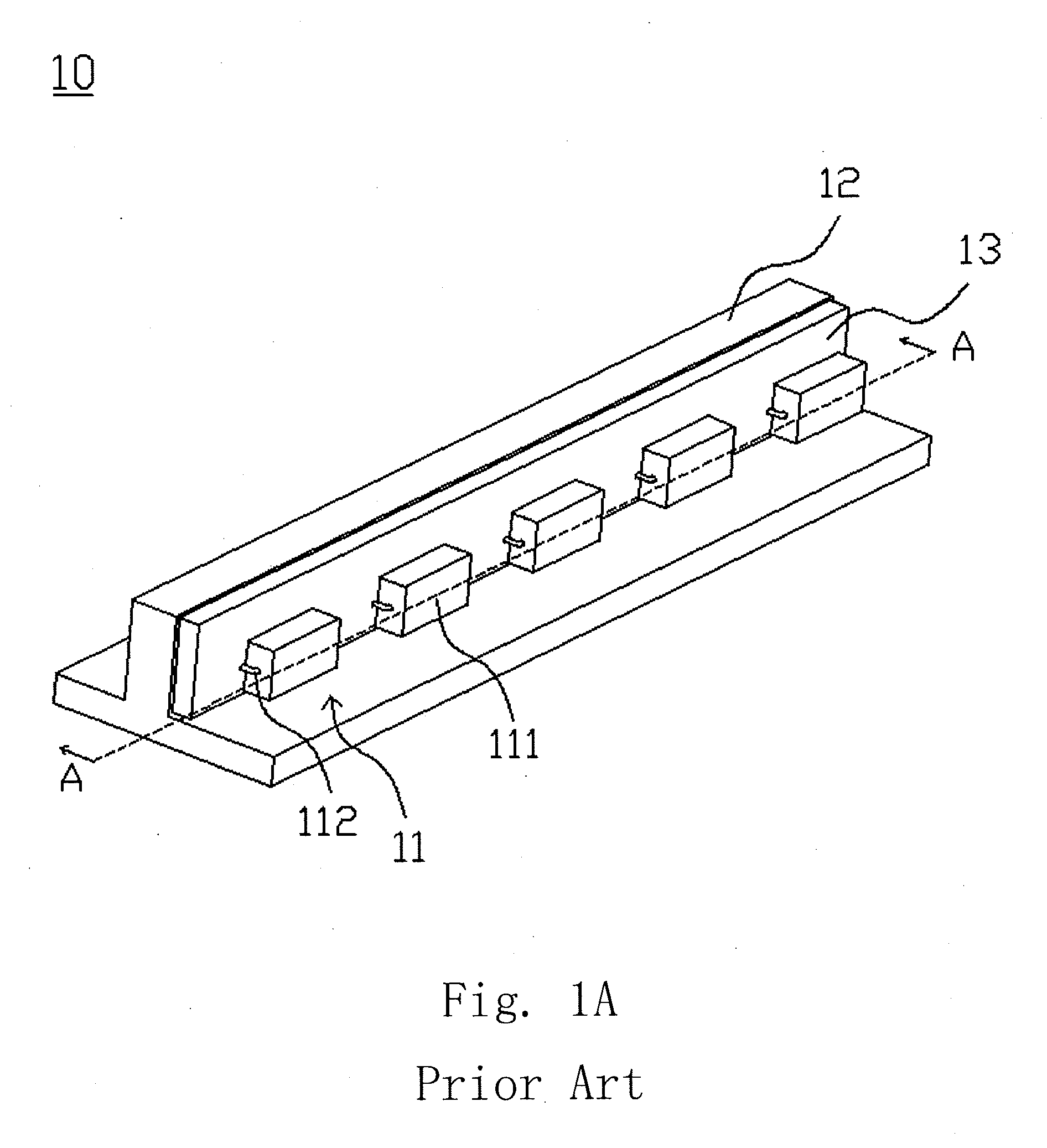
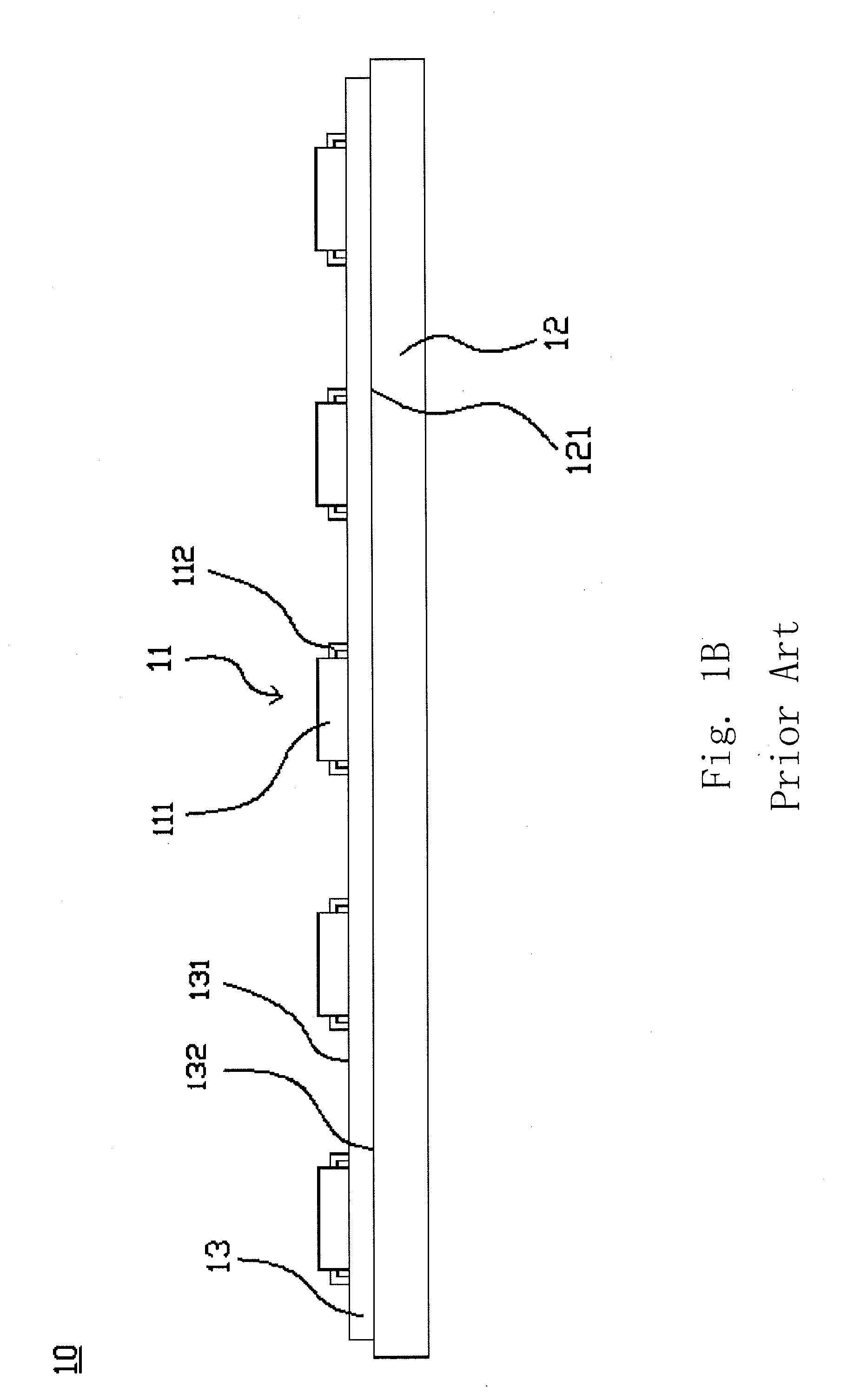
[0027]Referring to FIGS. 2A and 2B, schematic views of a light source heat-dissipation structure 20 of a side-light type backlight module according to a first preferred embodiment of the present invention are illustrated, wherein the light source heat-dissipation structure 20 is mainly applied to the field of liquid crystal display (LCD), and the light source heat-dissipation structure 20 comprises a light-source structure...


PUM


Abstract

The present invention provides a light source heat-dissipation structure of a backlight module having: a light-source structure, the heat-dissipation base and a carrier. The light-source structure has leads, respectively. The heat-dissipation base has a supporting surface, an attachment surface and first through holes. The carrier has second through holes, and the carrier is attached to the attachment surface of the heat-dissipation base. The light-source structure is set on the supporting surface of the heat-dissipation base, and the leads of the light-source structure pass through the first through holes and the second through holes and then electrically connect with the carrier. Hence, the heat-dissipation base may directly support and thermally contact the light-source structure for relatively enhancing the heat-dissipation efficiency of the light-source structure.

Description

FIELD OF THE INVENTION[0001]The present invention relates to a light source heat-dissipation structure of a backlight module, and more particularly to a light source heat-dissipation structure of a backlight module using a heat-dissipation base with high heat-dissipation efficiency to fix a light-source structure and to help a light-emitting diode for effectively conducting heat and dissipating heat.BACKGROUND OF THE INVENTION[0002]A liquid crystal display (LCD) is a kind of flat panel display (FPD), which shows images by the property of liquid crystal material. Comparing with other display devices, the liquid crystal display has the advantages in lightweight, compactness, low driving voltage and low power consumption, and thus has become the mainstream produce in the whole consumer market. However, the liquid crystal material of the liquid crystal display cannot emit light by itself, and must depend upon an external light source. Thus, the liquid crystal display further has a backl...

Claims


Application Information

Patent Timeline
Patent Type & Authority Applications(United States)
IPC IPC(8): F21V29/00
CPCG02F2001/133628G02F1/133603G02F1/133628
Inventor QUE, CHENGWEN
Owner TCL CHINA STAR OPTOELECTRONICS TECH CO LTD
Why Eureka
Try Eureka