Multi-core fiber optical coupling elements

a fiber optic coupling element and multi-core technology, applied in the field of integrated circuits and silicon chip technology, can solve the problems of affecting the performance of optical coupling elements, so as to improve optical coupling performance, simplify the package, and reduce the cost

Active Publication Date: 2012-10-04
GLOBALFOUNDRIES US INC
View PDF7 Cites 44 Cited by
  • Summary
  • Abstract
  • Description
  • Claims
  • Application Information

AI Technical Summary

Benefits of technology

[0017]In view of the foregoing and other problems, disadvantages, and drawbacks of the aforementioned background art, an exemplary aspect of the disclosed invention provides a means to optically i

Problems solved by technology

However, today's optical transceiver packages are bulky, complex and expensive.
Today's high-end supercomputer systems are being built with hundreds of thousands of individual optical fibers to transmit this data, at considerable expense.
Electrical data links perform well over short distances, but they reach a limit as the link distance and frequency increases.
However, current optical transceivers are bulky and expensive compared with their electrical counterparts.
However, a single core in the optical fiber increases the space that is used by the arrangement and can be expensive.
If the fiber touches the VCSEL array, then the VCSEL array may be damaged.
There is possible damage during assembly, and the optical fiber is not easily connectorized.
Another problem relates to the NA (numerical aperture) of the VCSEL that may be greater than a typical NA of a multi-mode fiber.
Therefore, given this mismatch in NAs, a coup

Method used


Image

  • Multi-core fiber optical coupling elements
  • Multi-core fiber optical coupling elements
  • Multi-core fiber optical coupling elements

Examples


Embodiment Construction

[0050]The invention will now be described with reference to the drawing figures, in which like reference numerals refer to like parts throughout. It is emphasized that, according to common practice, the various features of the drawing are not necessary to scale. On the contrary, the dimensions of the various features can be arbitrarily expanded or reduced for clarity.

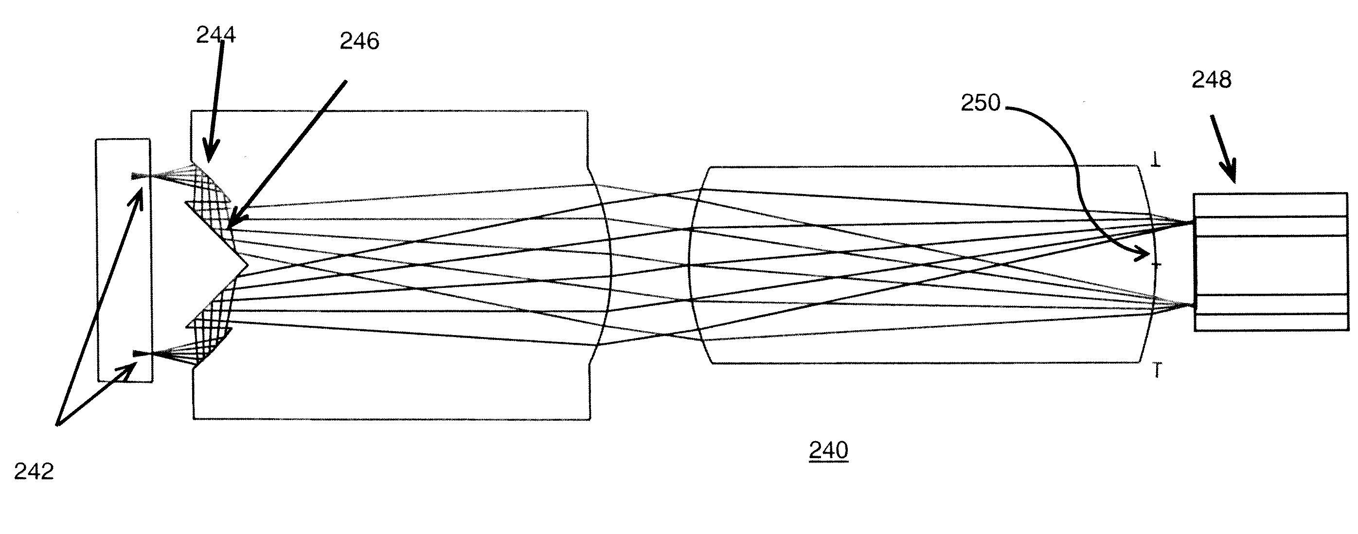
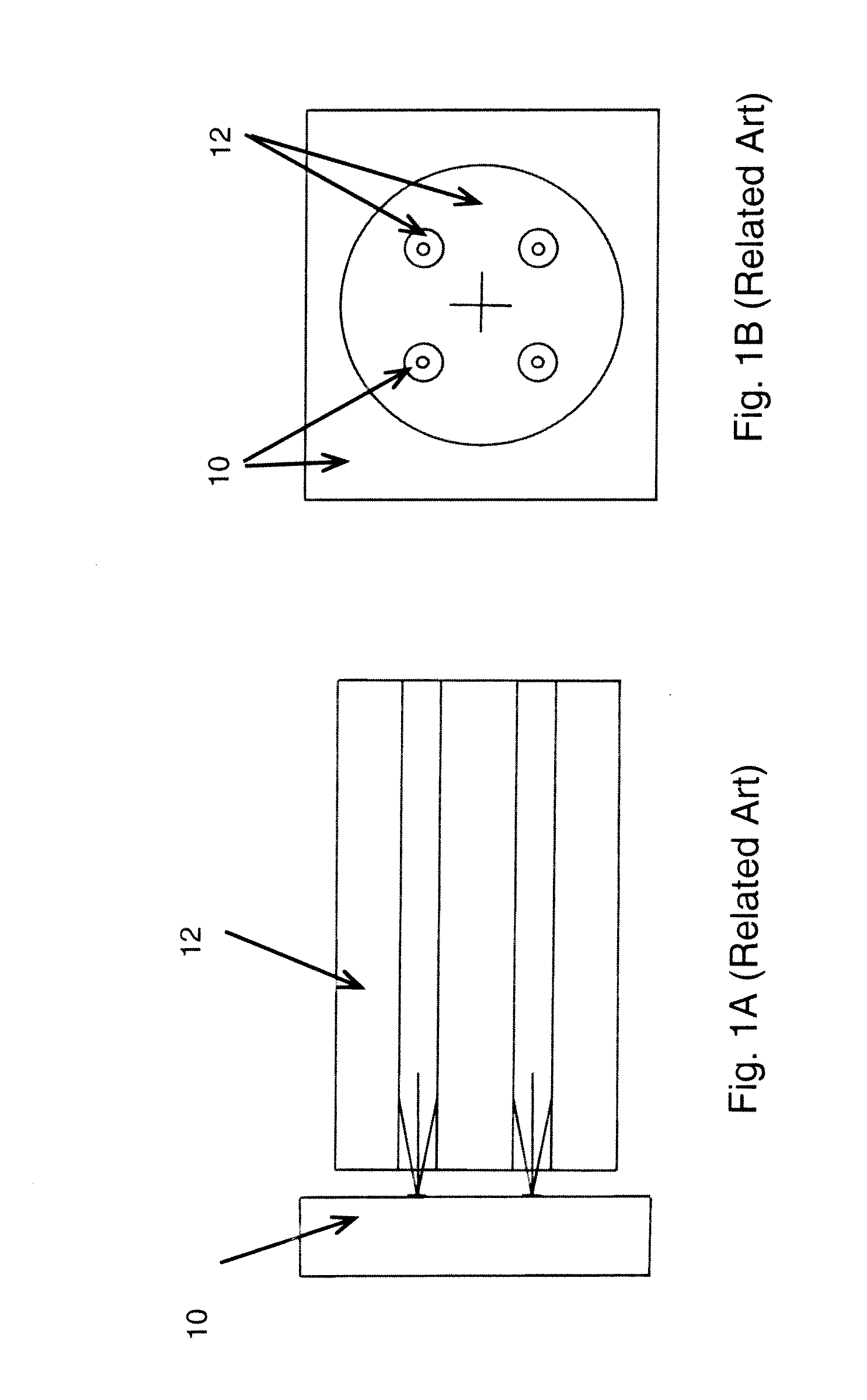
[0051]The current standard, for example, is a 12 channel optical transceiver mating with a 12 fiber ribbon cable, with each fiber containing only a single core. However, an exemplary aspect of the invention provides a means to interconnect a modified version of today's transceiver with an optical fiber containing multiple cores, thereby dramatically increasing the number of available optical channels without increasing the transceiver's package size.

[0052]Therefore, an exemplary embodiment in accordance with the invention provides an apparatus and technique to optically interconnect multi-core optical fiber with a compa...


PUM


Abstract

An optical coupling system includes a first unit including a source of light or a first multi-core optical fiber, each of the source and the first multi-core optical fiber including at least a first aperture, a second unit including a second multi-core optical fiber including at least a second aperture corresponding to the first aperture of the first unit, and a lens array unit redirecting light between the first unit and the second unit, the lens array unit substantially matching light rays transmitted or received between the first aperture of the first unit and the corresponding second aperture of the second unit.

Description

BACKGROUND OF THE INVENTION[0001]1. Field of the Invention[0002]The disclosed invention relates generally to integrated circuits and silicon chip technology, and more particularly, but not by way of limitation, the packaging of optoelectronic devices in a dense and integrated manner.[0003]2. Description of the Related Art[0004]Optical transceivers are increasingly used to enable data communication between and within computers. An optical transceiver can transmit and receive data using optical fiber rather than electrical wire. The optical fiber can be used to facilitate the transfer of information in light beams, rays or pulses along solid transparent fibers or cables. One of the major advantages of optical technology is its high transfer rate.[0005]However, today's optical transceiver packages are bulky, complex and expensive. The performance of high-end computers systems continues to improve as the number of processing cores (and their speed) is increased. This increase in the num...

Claims


Application Information

Patent Timeline
IPC IPC(8): G02B6/32G02B13/22
CPCG02B13/26G02B13/22G02B6/02042G02B6/4214G02B6/4243G02B6/425
Inventor BUDD, RUSSELL A.LIBSCH, FRANK R.
Owner GLOBALFOUNDRIES US INC
Why Eureka
Try Eureka