
Receiver and receiving method for receiving data in a broadcast system using incremental redundancy received through a unicast system

a technology of receiving method and receiving method, which is applied in the direction of coding, code conversion, fault response, etc., to achieve the effect of increasing the probability of error-free reception/reconstruction of data by a mobile receiver

Active Publication Date: 2012-10-04
SONY CORP
View PDF11 Cites 39 Cited by
  • Summary
  • Abstract
  • Description
  • Claims
  • Application Information

AI Technical Summary

Benefits of technology

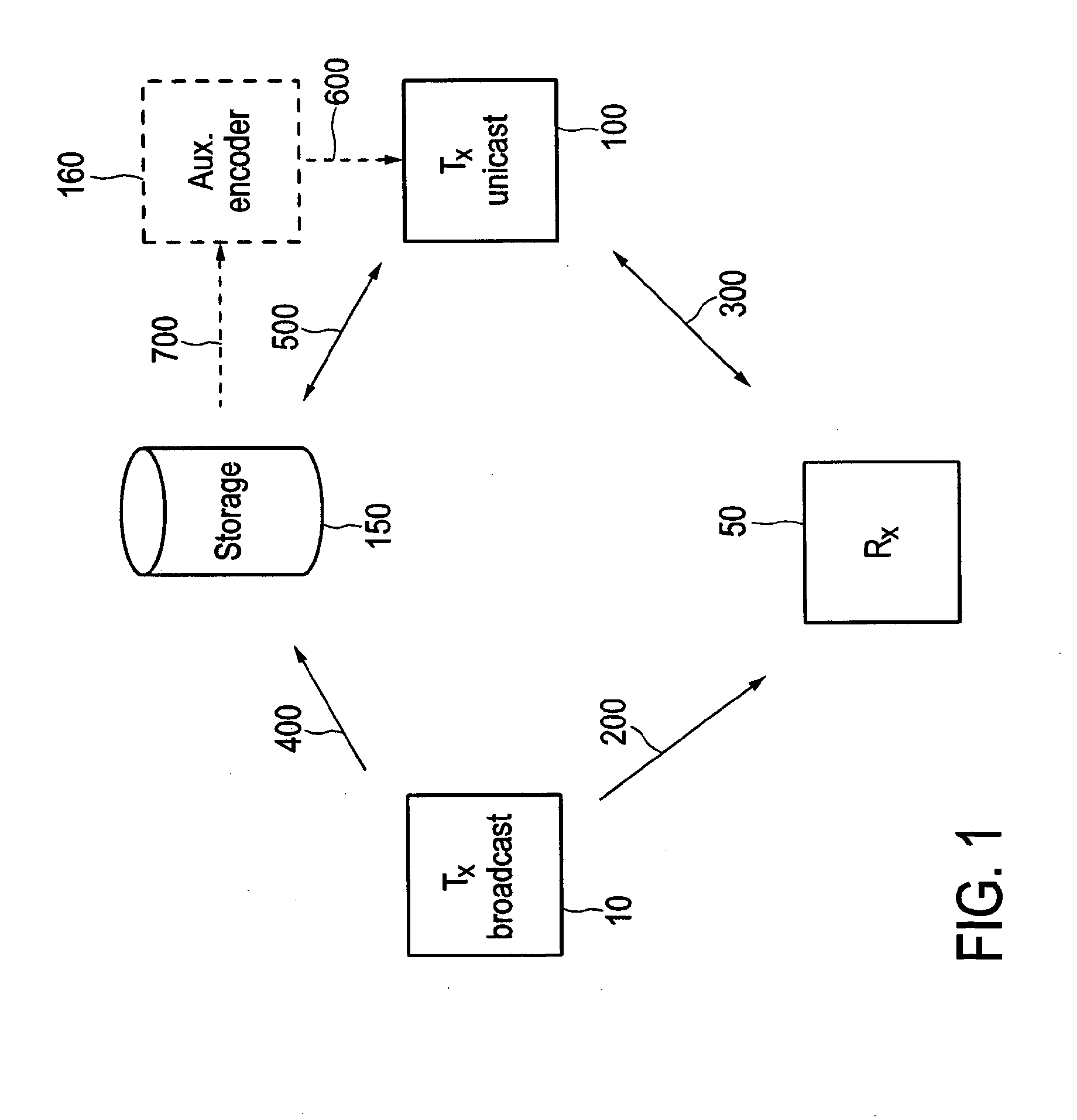
[0035]The present invention is based on the idea to enable a mobile receiver, for instance an in-car receiver or a handheld receiver (e.g. in a mobile phone or a PDA) in a broadcast system to decode broadcast data even under severe transmission channel conditions by improving the provided error correction measures. In particular, it is proposed to provide a sufficient amount of redundancy on request of the receiver to increase the robustness of the code. Said additional redundancy is provided by the data transmission system after a feedback from the receiver is received requesting additional redundancy. Said additional redundancy is, however, not broadcasted over the broadcast system, but is transmitted over a unicast system to the requesting receiver only. This receiver can use the additional redundancy to perform another decoding of previously (through the broadcast system) received codeword. Hence, if reception or reconstruction (decoding) of received broadcast data is erroneous or could only be made with insufficient quality, the receiver can repeat decoding using, in addition to the previously received codeword, the requested additional redundancy.
[0056]Preferably, the invention is applied for broadcasts of non-real-time data, i.e. of data that are generally not replayed by the receiver in real-time, but are buffered in the receiver until the user requests a replay at any later time (“Push Video on Demand”). In such an application the waiting time for obtaining and using any auxiliary codeword portions in case of decoding errors does not cause any inconvenience to the user.

Problems solved by technology

Hence, if reception or reconstruction (decoding) of received broadcast data is erroneous or could only be made with insufficient quality, the receiver can repeat decoding using, in addition to the previously received codeword, the requested additional redundancy.

Method used


Image

  • Receiver and receiving method for receiving data in a broadcast system using incremental redundancy received through a unicast system
  • Receiver and receiving method for receiving data in a broadcast system using incremental redundancy received through a unicast system
  • Receiver and receiving method for receiving data in a broadcast system using incremental redundancy received through a unicast system

Examples


embodiment 142

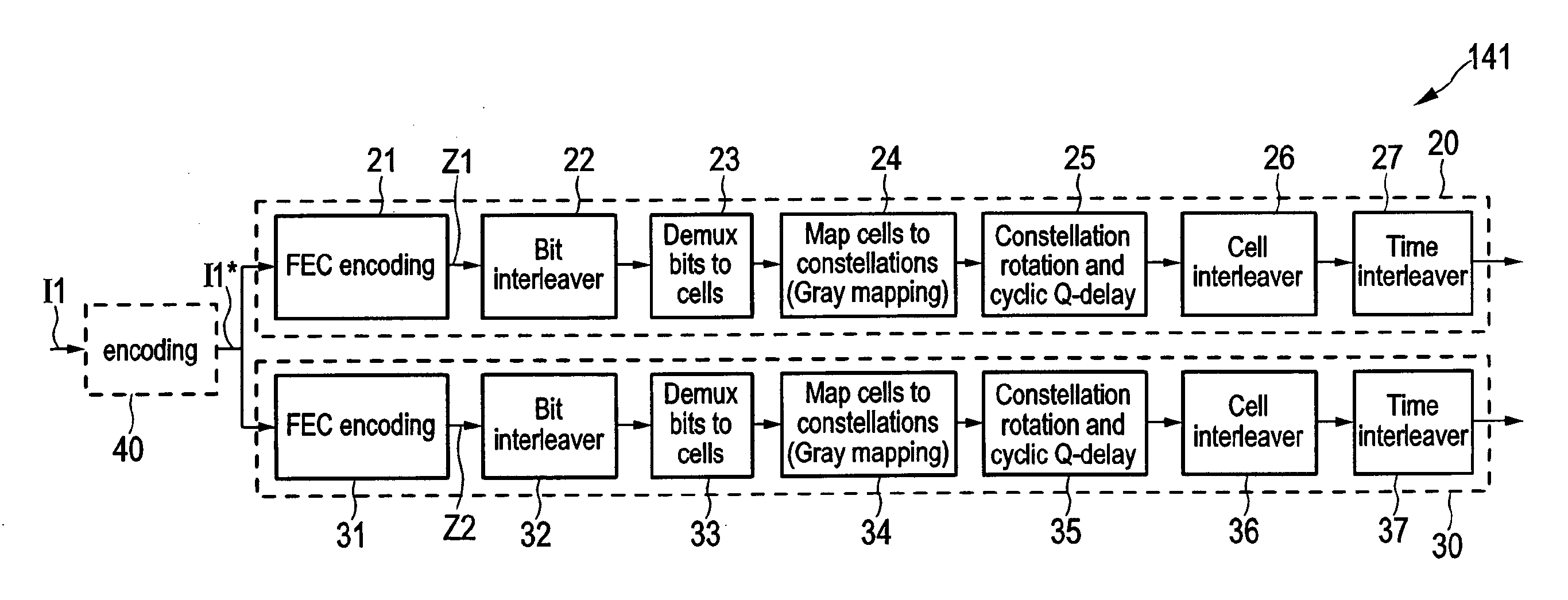
[0105]In an alternative embodiment 142 as depicted in FIG. 11 the encoding unit 30a only comprises the FEC encoder 31 for generation of the codeword Z2 (or only of the auxiliary codeword portion A or of the auxiliary parity portion Pa, respectively). In this case the output data of the encoding unit 30a is not transferred to the data storage 150 by a broadcast, but is transferred via a different channel, e.g. through a wired line connecting the broadcast transmitter 10 and the data storage(s) 150. Also in this case the data received by the data storage(s) 150 can be considered to be highly reliable.

embodiment 143

[0106]In a further embodiment 143 of the encoder 14 as depicted in FIG. 12 only a single encoding unit 20 is provided for generation of the basic codeword portion B only, i.e. comprising only a data portion D and a basic parity portion Pb. In this case, the auxiliary codeword portion A is not generated by the broadcast transmitter 10, in particular its encoder 14, but generally the data portion D and / or the basic codeword portion B is stored in the data storage 150. Hence, if an auxiliary codeword portion A is later requested by the receiver 50, this auxiliary codeword portion A must be generated on the fly from the stored data portion D or the stored basic codeword portion B as will be explained below. Here, using stored basic codeword portions B is preferred for this generation of auxiliary codeword portions on the fly, since often this requires less time if these portions are accumulated to obtain a “total” codeword, as is often the case (see §6.1.2.1 of the DVB-T2 standard).

[010...

embodiment 144

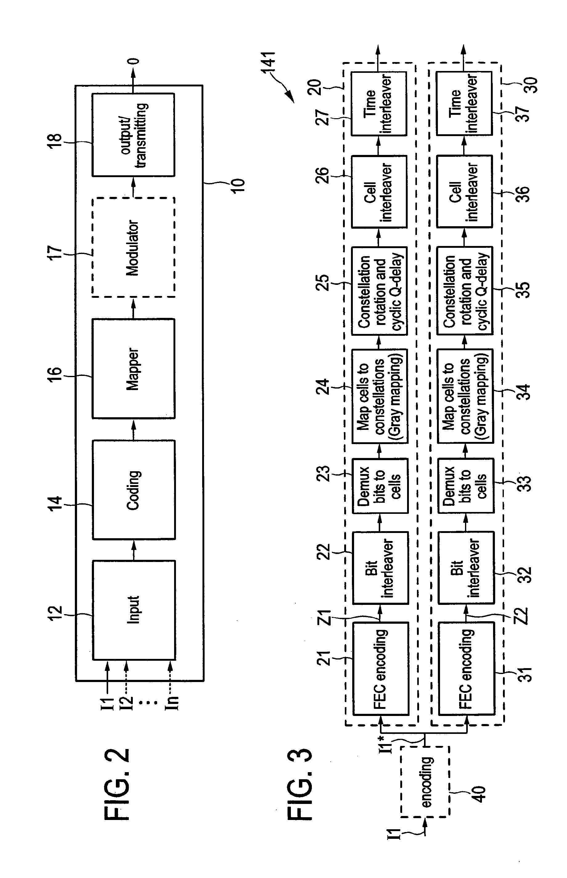
[0113]A still further embodiment 144 of an encoder 14 is illustrated in FIG. 13. Said encoder 144 is adapted such that it generates two or more auxiliary parity subportions Pa1, Pa2, Pa3 in addition to the data portion D and the basic parity portion Pb thus forming a codeword Z3. Hence, comparing the codewords Z2 and Z3, the auxiliary parity sub-portions Pa1, Pa2, Pa3 of the codeword Z3 can be seen as segments of the auxiliary parity portion Pa of the codeword Z2, having in total the identical content, although generally the auxiliary parity sub-portions Pa2 and Pa3 can also be additional auxiliary parity portions in addition to the auxiliary parity portion Pa1 that (alone) corresponds to the auxiliary parity portion Pa. It shall, however, be noted that the other embodiments 141, 142, 143 of the encoder 14 shown in FIGS. 3, 11, 12 are generally also able to generate two or more auxiliary parity sub-portions Pa1, Pa2, Pa3 (rather than a single auxiliary parity portion Pa) in addition...


PUM


Abstract

A receiver includes: a broadcast receiver receiving a receiver input data stream segmented into frames, wherein basic codeword portions of codewords are mapped onto the frames, a codeword including at least a basic codeword portion generated from an input data word according to a first code; a data demapper demapping the basic codeword portions; a decoder error correction code decoding the codewords into output data words of at least one output data stream in a regular decoding using the basic codeword portion in a codeword; a check unit checking if the regular decoding of a codeword is erroneous; a unicast request unit requesting, if the regular decoding of a codeword is erroneous, an auxiliary codeword portion of the erroneously decoded codeword for incremental redundancy in an additional decoding; a unicast receiver unit receiving an auxiliary codeword portion of the erroneously decoded codeword.

Description

CROSS-REFERENCE TO RELATED APPLICATION[0001]The present application claims the benefit of the earlier filing date of European patent application 09 180 151.4 filed in the European Patent Office on Dec. 21, 2009 and is a national phase application of International patent application PCT / EP 2010 / 068519 filed on Nov. 30, 2010, the entire content of which applications is incorporated herein by reference.BACKGROUND[0002]1. Field of the Disclosure[0003]The present disclosure relates to a receiver and a corresponding receiving method for receiving data in a broadcast system. The present disclosure relates further to a data transmission system and a corresponding data transmission method for transmitting and receiving data. Still further, the present disclosure relates to a computer program for implementing said receiving method on a computer.[0004]The present disclosure relates, for instance, to the field of Digital Video Broadcasting (DVB) utilizing Orthogonal Frequency Division Multiplex...

Claims


Application Information

Patent Timeline
IPC IPC(8): H03M13/05G06F11/10
CPCH04L1/1893H03M13/1102H03M13/6393H03M13/6552H04L1/1819H04L1/02H03M13/255H03M13/253H04L2001/0093H03M13/152H03M13/6306
Inventor LOGHIN, NABILSTADELMEIER, LOTHARROBERT, JOERG
Owner SONY CORP
Learn More