
Phase shift RF ion trap device

a technology of ion trap and phase shift, which is applied in the direction of separation process, mass spectometer, dispersed particle separation, etc., can solve the problems of space-charge repulsion interference, trap can be filled, and some ions are expulsed

Inactive Publication Date: 2012-10-11
HUMANIX
View PDF2 Cites 20 Cited by
  • Summary
  • Abstract
  • Description
  • Claims
  • Application Information

AI Technical Summary

Benefits of technology

"The patent describes an ion trap that can trap electrically charged particles or ions using a combination of electrodes and a voltage supply. The ion trap has a small gap where ions can be injected and trapped repeatedly. The voltage supply provides RF voltage to the electrodes, which are positioned around a central axis or in a continual shape. The field radius decreases from the trap center to the ends in a longitudinal direction. The technical effects of this invention include improved trapping efficiency, reduced space requirement, and improved stability of the ion trap."

Problems solved by technology

When many ions are accumulated, space-charge repulsion interferes with trapping more ions and, in some cases, expulses some ions.
However, even the newest and conventional linear ion traps share one disadvantage: Before ion ejection and detection, the trap can be filled only during a short time-lapse.
Thus, ion accumulation is limited by the ion speed and the length of the trap.
Further, its construction is complicated and expensive due to its inherent multiple sections, segments mounting, RF and DC voltage supply.
Another weak point for LIT, working as ion source for a mass analyzer, is that the ion ejection of the axially dispersed beam is not always completely effective.
Also linear ion traps made of multipoles are difficult to mount due to the number and proximity of the rod electrodes.

Method used


Image

  • Phase shift RF ion trap device
  • Phase shift RF ion trap device
  • Phase shift RF ion trap device

Examples


Embodiment Construction

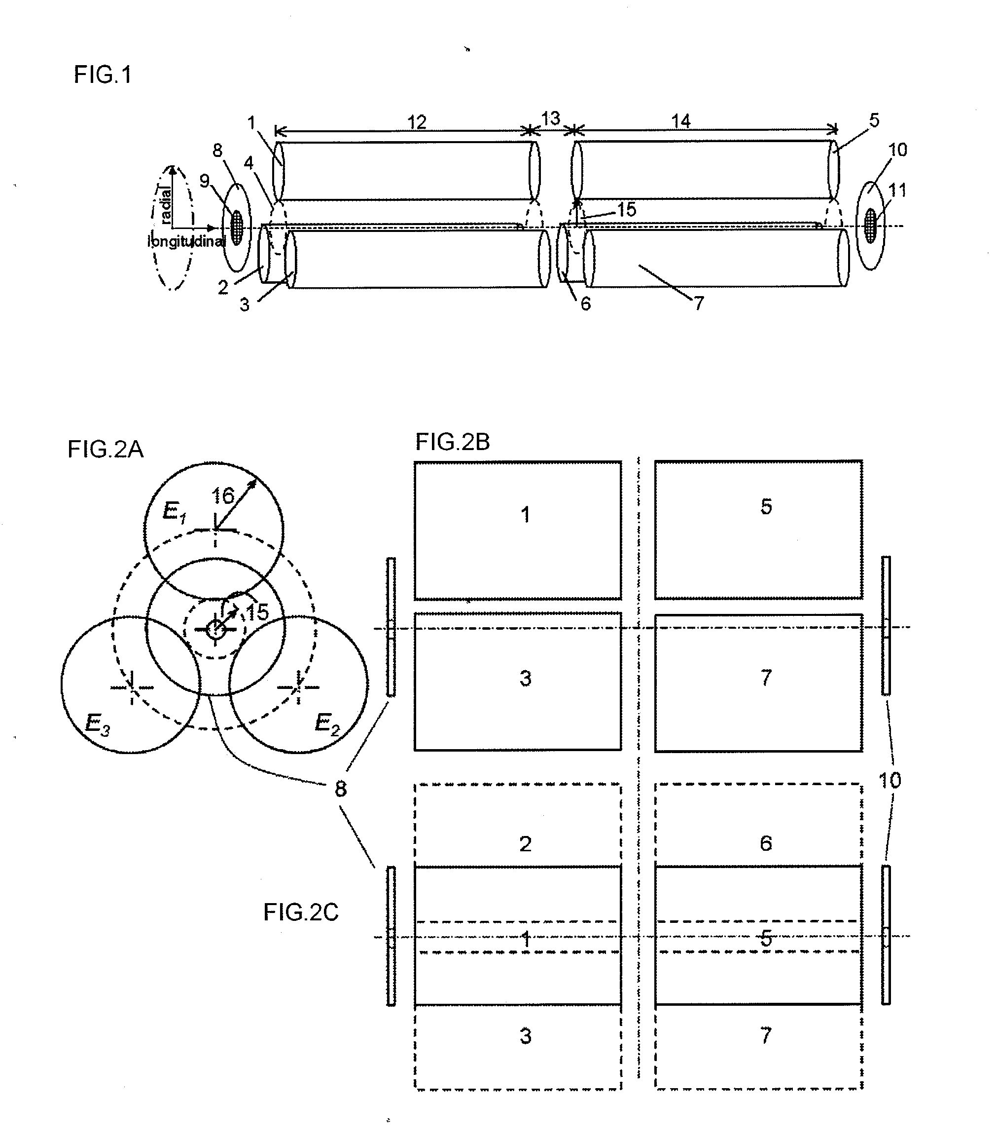
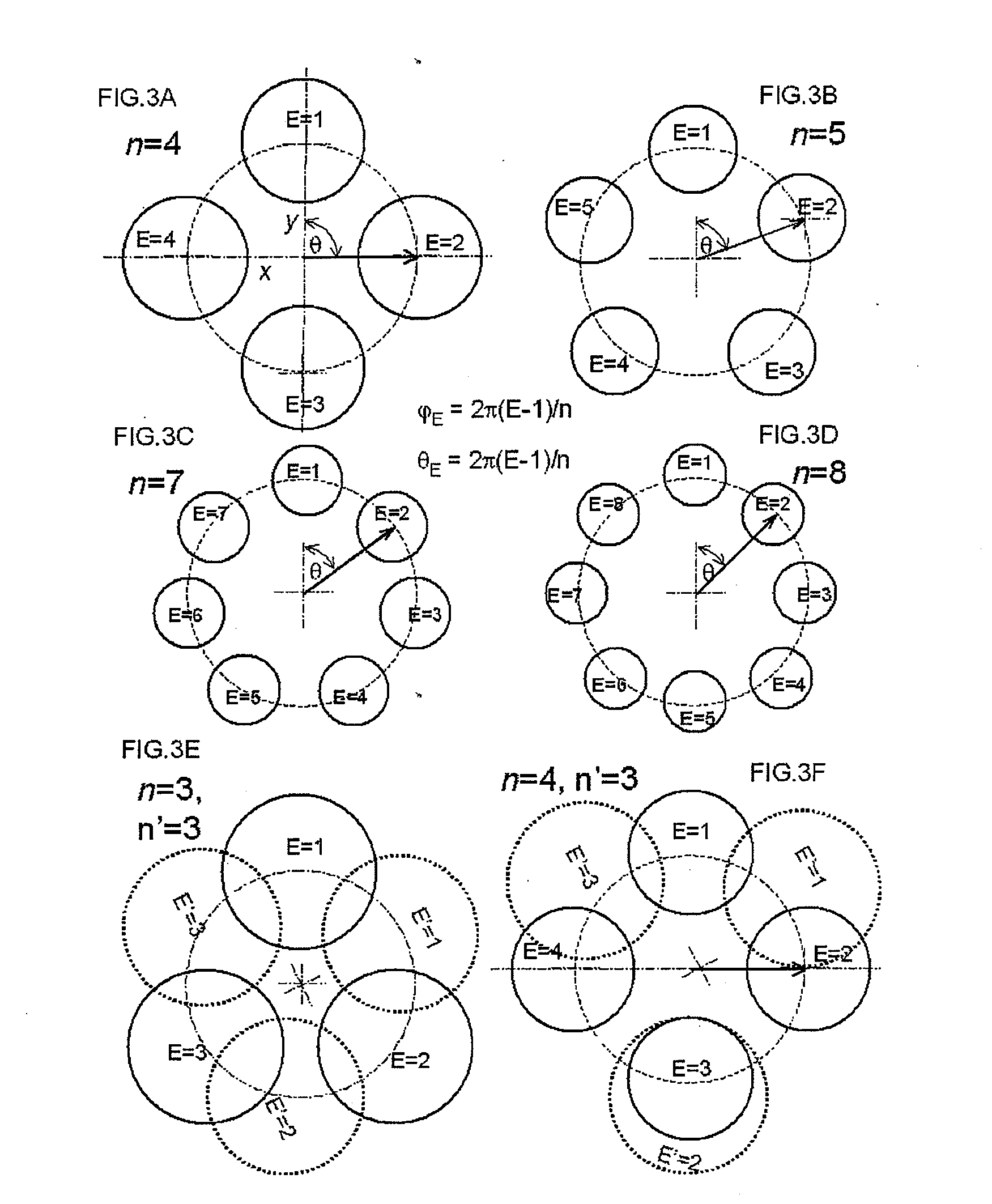
[0086]An embodiment of the present invention is an ion trap comprising at least two ion guides separated by one or more gaps and each ion guide comprises three or more (“n”) rod electrodes that are numbered “E” consecutively clockwise or counterclockwise from 1 to “n”.

[0087]The electrode is preferably in a rod shape. Each of the ion guides may have an equal or unequal number of electrodes. The rod electrodes are positioned in radial locations around a field space. The electrodes can be asymmetrically or symmetrically positioned at angular position (θ), where θE=2π(E−1) / n radian is determined with a central axis as the origin. In the case of asymmetric angular positioning, the rods width and shape preferably be changed in order to fulfil two conditions, the electrodes with different phase cannot touch each other and the electrodes may surround the field space. In the case of three-rod electrodes in a symmetrical position, the rods are positioned at angular positions of 0, 120 and 240...


PUM


Abstract

A novel ion trap made of at least two ion guides sets separated by a gap and each guide consists of three or more rods-like multipole carrying radio frequency (RF) voltages with delayed phases. The injected ions are axially or orthogonally, contained by pulsed DC and / or RF voltages. When the ions translational energy is damped due to collisions with a low-pressurized inert gas, the 3-D RF field in the gap, which is created by the special rod and electricity arrangement, can trap the ions and compact them in a dense ion cloud. Because the ions are trapped in the small gap, new ions can be injected and the trapping cycle can be repeated many times before the ion ejection. The ions are ejected from the gap orthogonally or axially. This ion trap is useful for mass spectrometry and beam physics, specifically for high efficient ion accumulation and focusing the ions in a small space.

Description

BACKGROUND OF THE INVENTION[0001]1. Field of the Invention[0002]This invention relates to ion trap devices, more particularly, to such devices that are formed by three or more electrode rods ion guide with phase shifted RF voltages.[0003]2. Description of the Related Art[0004]Multipole ion guides have been used in mass spectrometry to contain the ions in radial direction by means of RF electric fields, where the ions stably oscillate and fly through the system, thus the ions are transported to the different stages of the spectrometer. Traditionally, the multipole ion guides have been used to construct linear ion traps (LIT) by adding entrance and exit ion optics to the ion guide, thereby axial trapping is accomplished.[0005]In bio-analytical sciences, high sensitivity is a key point for success. The signal-to-noise ratio can be considerably increased by analyte accumulation inside of a LIT that is a high sensitive and widely used mass spectrometry technique. The LIT is considered to...

Claims


Application Information

Patent Timeline
Patent Type & Authority Applications(United States)
IPC IPC(8): H01J49/36
CPCH01J49/4225
Inventor MASUJIMA, TSUTOMUSALAZAR, GARY ABDIEL
Owner HUMANIX
Learn More