
Detection device

a detection device and detection technology, applied in the direction of optical radiation measurement, instruments, spectrometry/spectrophotometry/monochromators, etc., to achieve the effect of improving detection accuracy

Active Publication Date: 2012-10-11
SEIKO EPSON CORP
View PDF5 Cites 2 Cited by
  • Summary
  • Abstract
  • Description
  • Claims
  • Application Information

AI Technical Summary

Benefits of technology

[0008]According to some of the aspects of the invention, it is possible to provide a detection device or the like capable of real-time measurement with improved reliability of the inspection.
[0011]As described above, by performing the first mode and the second mode alternately, the fluid sample once adsorbed to the optical device can be made to break away. In such a manner, it is possible to clean up the optical device after the inspection, and it becomes possible to repeatedly perform a subsequent inspection without leaving the influence of the previous inspection. Therefore, by performing the first and second modes alternately in a repeated manner, the real-time inspection becomes possible. Moreover, since it is possible to clean up the optical device after the inspection, the determination on whether or not the inspection target material exists in the fluid sample at a concentration equal to or higher than a predetermined concentration can be performed with high reliability.
[0013](3) In one aspect of the invention, in the detection device according to the above aspect of the invention, the optical device can be provided with a metal nanostructure having projections in a range of 1 through 1000 nm. According to this configuration, an enhanced electric field is formed around the projection of the metal nanostructure, and the signal intensity of the Raman scattering light enhanced by the enhanced electric field becomes stronger.
[0015](5) In one aspect of the invention, in the detection device according to the above aspect of the invention, the control section can stop driving the negative pressure generation section in the first mode. Some inspection target materials easily break away from the optical device, and the materials break away from the optical device only with, for example, the fluid transport amount per unit time, which is caused by the negative pressure generation section such as a fan, exceeding 0. In such a case, the control section stops driving the negative pressure generation section in the first mode. If the second mode is performed prior to the first mode, the flow velocity of the fluid sample on the optical device can be assured using the flow amount and the inertia in the second mode. Thus, the material in the fluid sample can be adsorbed to the optical device even if the drive of the negative pressure generation section is stopped.
[0016](6) In one aspect of the invention, in the detection device according to the above aspect of the invention, the control section can perform switching from the first mode to the second mode in response to a level of the signal from the light detection section exceeding a first threshold level. The material in the fluid sample sucked therein is adsorbed to the optical device in the first mode, and the signal intensity from the light detection section increases in conjunction therewith. The inspection of presence or absence of the inspection target material can be performed before the signal level reaches the first threshold level. Therefore, if the level of the signal from the light detection section exceeds the first threshold level, switching from the first mode to the second mode is allowed. In the second mode, by making the material once adsorbed break away, the optical device can be cleaned up prior to the subsequent inspection.
[0022](12) In one aspect of the invention, in the detection device according to the above aspect of the invention, the control section can perform switching in order of the second mode, the first mode, and the second mode. As described above, due to the second mode performed prior to the first mode, the optical device is cleaned up prior to the detection to thereby improve the detection accuracy, and due to the second mode performed after the first mode, it is possible to clean up the optical device prior to the subsequent detection. Therefore, an advantage to the real-time detection can be obtained.

Problems solved by technology

However, according to the detection device described above, although it is possible to detect whether or not the sample molecules adsorbed to the metal nanoparticles of the surface plasmon resonance sensor are pollutants, the detection can be performed only once.

Method used


Image

  • Detection device
  • Detection device
  • Detection device

Examples


first experimental example

4.1. First Experimental Example

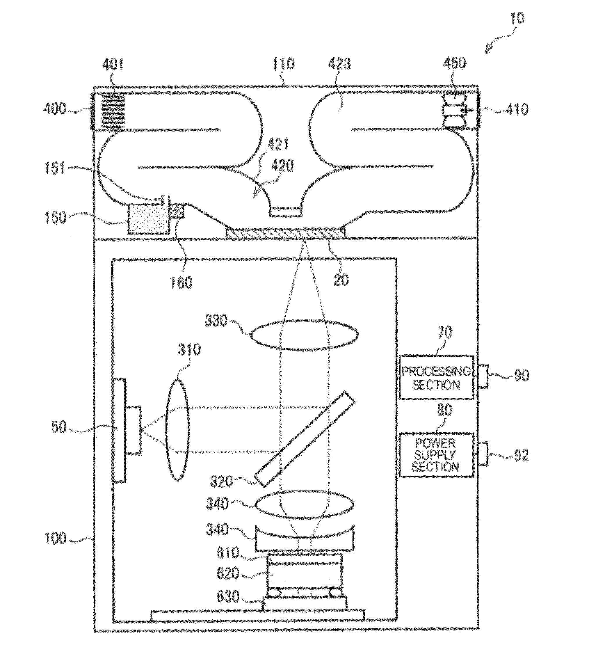
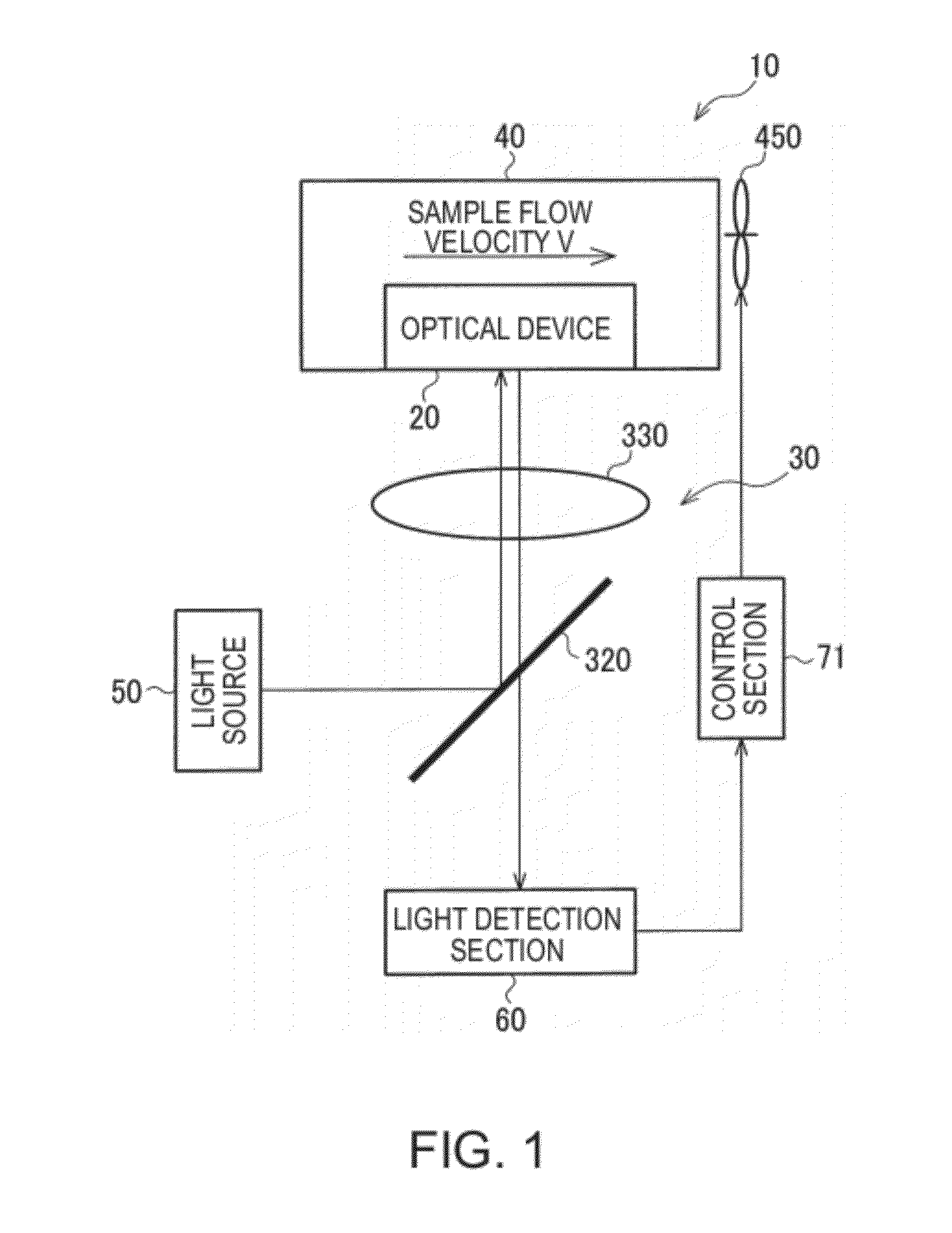
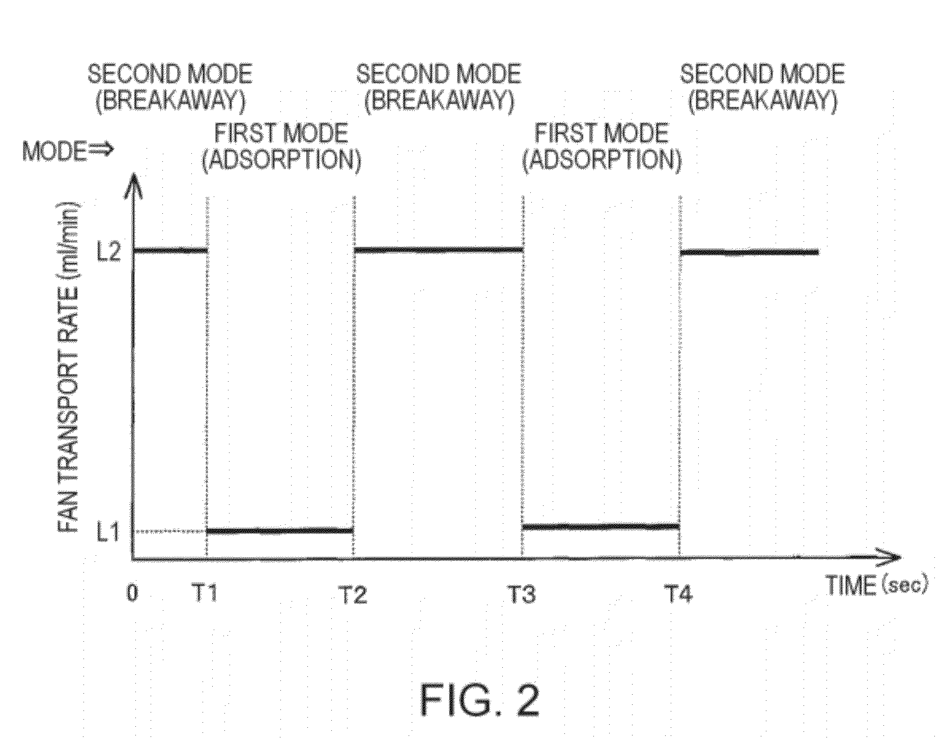
[0072]FIG. 9 shows a result of actual measurement using lactic acid gas molecules as the sample molecules 1 as the inspection target material performed in accordance with the time chart of the first mode (the adsorption mode) and the second mode (the breakaway mode) shown in FIG. 8. As the light source 50 shown in FIG. 6, a He-Ne laser with an excitation wavelength of 632.8 nm and intensity of 0.2 mW is used. The measurement exposure time in the light detection section 60 shown in FIG. 6 is set to 5 seconds, and the material of the optical device 20 shown in FIG. 6 is Ag. The fluid transport rate L1 of the fan 450 in the first mode (the adsorption mode) is set to 20 ml / min, and the fluid transport rate L2 of the fan 450 in the second mode (the breakaway mode) is set to 200 ml / min.

[0073]As shown in FIG. 8, the experiment starts with the breakaway mode for 30 seconds. The mode is switched to the adsorption mode of L1: 20 ml / min, 30 seconds later. FIG. 9 ...

second experimental example

4.2. Second Experimental Example

[0077]In the same device as in the first experimental example, isopropyl alcohol (IPA) molecules are used as the sample molecules 1 as the inspection target material, and the measurement is performed setting the measurement exposure time to 10 seconds. In the second experimental example, as shown in FIG. 10, the fluid transport rate L1 of the fan 450 in the first mode (the adsorption mode) is set to 0 ml / min, and the fluid transport rate L2 of the fan 450 in the second mode (the breakaway mode) is set to 20 ml / min. The fluid transport rates L1, L2 in the second experimental example are set lower than the respective fluid transport rates L1, L2 in the first experimental example.

[0078]The reason therefor is as follows. The IPA molecules have weak adsorption force to the optical device 20 than that of the lactic acid molecules. The molecules with weak adsorption force such as the IPA molecules often fail to be detected since the breakaway is promoted eve...

third experimental example

5.2. Third Experimental Example

[0087]FIG. 17 shows a result of an actual measurement using pyridine molecules as the reference molecules performed in accordance with the time chart of the first mode (the adsorption mode) and the second mode (the breakaway mode) shown in FIG. 16. It should be noted that the sample molecules are not particularly assumed in the third experimental example. As the light source 50 shown in FIG. 6, a He—Ne laser with an excitation wavelength of 632.8 nm and intensity of 2 mW is used. The measurement exposure time in the light detection section 60 shown in FIG. 6 is set to 10 seconds, and the material of the optical device 20 shown in FIG. 6 is Ag. The fluid transport rate L1 of the fan 450 in the first mode (the adsorption mode) is set to 20 ml / min, and the fluid transport rate L2 of the fan 450 in the second mode (the breakaway mode) is set to 2000 ml / min.

[0088]As shown in FIG. 16, the experiment starts with the breakaway mode for 30 seconds. The mode is ...


PUM


Abstract

A detection device includes an optical device, a suction section adapted to suck the fluid sample in the optical device, a light source adapted to irradiate the optical device with light, a light detection section adapted to detect light emitted from the optical device, and a control section adapted to perform drive control on the suction section. The optical device emits light reflecting the fluid sample to be adsorbed. The control section sets a suction flow velocity of the fluid sample on the optical device to V1 in a first mode including a period of performing detection by the light detection section, sets the suction flow velocity of the fluid sample on the optical device to V2 (V2>V1) in a second mode, and switches between the first mode and the second mode based on a signal from the light detection section.

Description

BACKGROUND[0001]1. Technical Field[0002]The present invention relates to a detection device particularly suitable for detection of a trace substance.[0003]2. Related Art[0004]In recent years, as one of sensitive spectroscopic techniques for detecting low-density sample molecules, surface enhanced Raman scattering (SERS) spectroscopy using surface plasmon resonance (SPR), in particular localized surface plasmon resonance (LSPR), has been attracting attention (Japanese Patent No. 3714671, JP-A-2000-356587). The SERS denotes a phenomenon that the Raman scattering light is enhanced 102 through 1014 times on a metal surface having a structure of providing unevenness in nanometer scale. The sample molecules are irradiated with an excitation light with a single wavelength such as a laser. The light with a scattering wavelength (the Raman scattering light) shifted from the wavelength of the excitation light as much as the molecular vibration energy of the sample molecules is spectroscopical...

Claims


Application Information

Patent Timeline
IPC IPC(8): G01J3/44G01N21/55G01N21/05G01N21/27
CPCG01N21/658
Inventor YAMADA, KOHEIHANO, YOSHIFUMI
Owner SEIKO EPSON CORP
Features
  • Generate Ideas
  • Intellectual Property
  • Life Sciences
  • Materials
  • Tech Scout
  • Unparalleled Data Quality
  • Higher Quality Content
  • 60% Fewer Hallucinations
Learn More