
Photon Detector with a Paralyzable Photon-Sensitive Element, in particular SPAD, and Distance Measuring Device Comprising said type of Photon Detector

a technology of paralyzing and sensitive elements, applied in the field of photon detectors, can solve the problems of insufficient reliable measurement of distance measuring devices, and achieve the effect of reducing the number of refractions

Inactive Publication Date: 2012-10-18
ROBERT BOSCH GMBH
View PDF3 Cites 10 Cited by
  • Summary
  • Abstract
  • Description
  • Claims
  • Application Information

AI Technical Summary

Benefits of technology

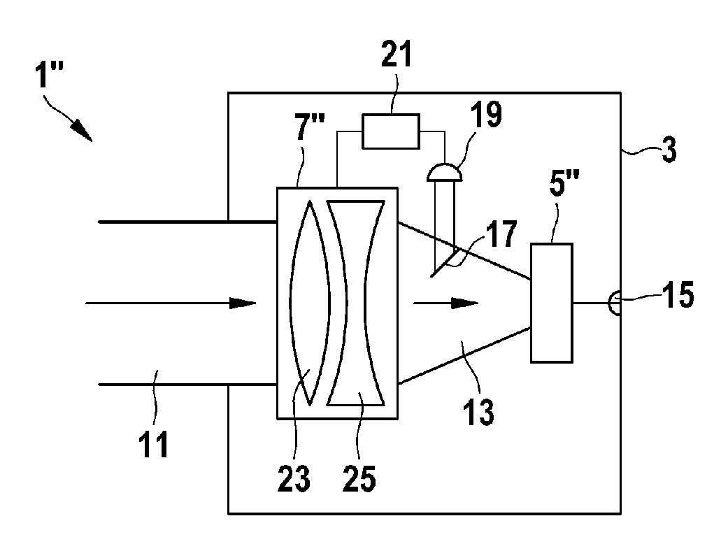
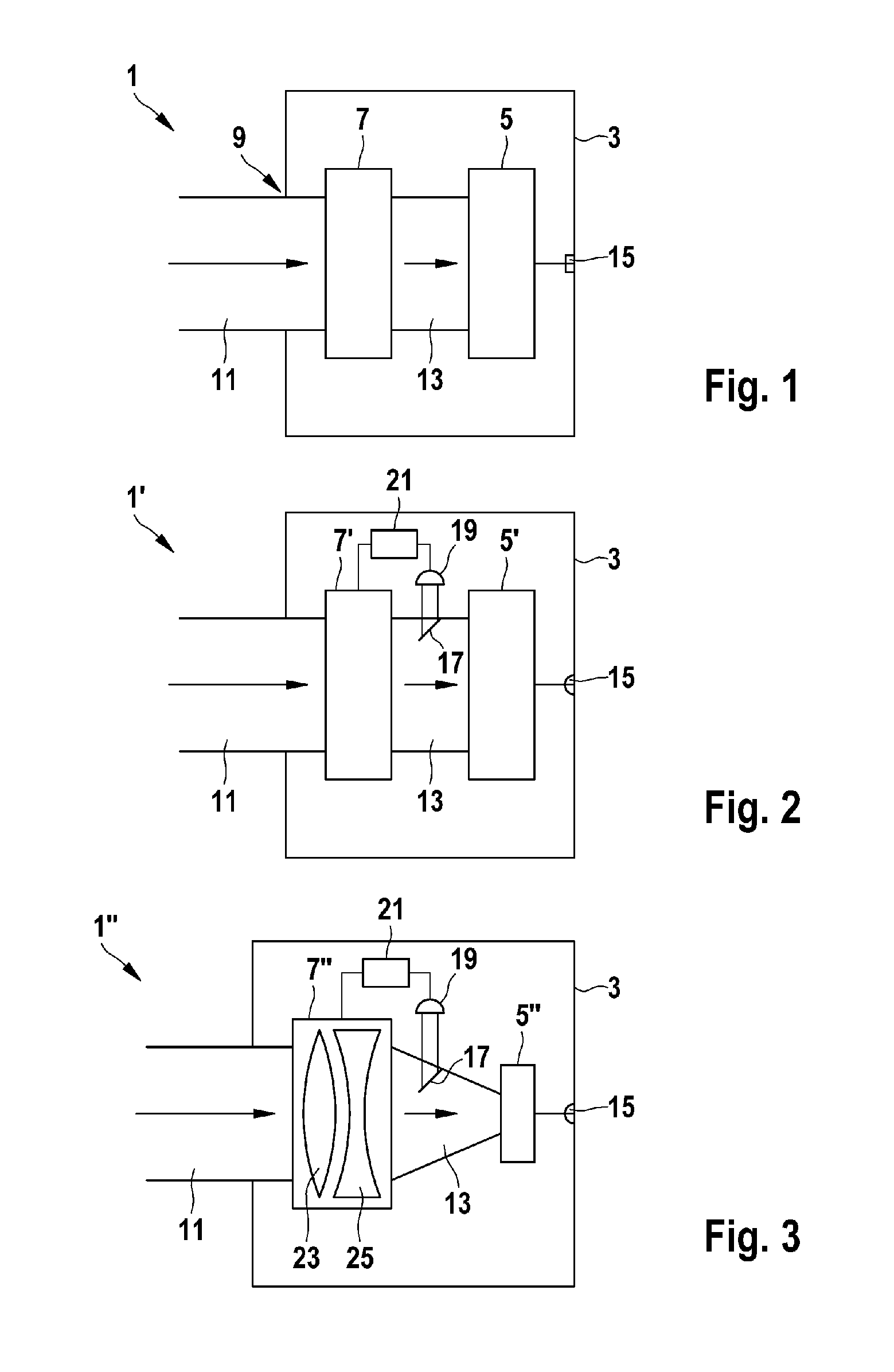
[0013]It can be advantageous to configure the photon detector in such a way that the photon intensity transmitted by the photon transmission element and impinging on the photon-sensitive element is varied in a manner dependent on the photon intensity impinging on the photon transmission element. In other words, by way of example, the absorption properties or the defocusing properties of the photon transmission element can be varied depending on the incident photon intensity. By way of example, the photon transmission element can absorb to a greater extent or defocus to a greater extent at high incident photon intensity than at low photon intensity. In this way, the photon intensity impinging on the paralyzable photon-sensitive element can be adapted to the properties of said photon-sensitive element by means of the photon intensity that impinges on the photon detector from outside being suitably reduced by the photon transmission element beforehand.
[0023]If the photon detector described is used for example in a distance measuring device, sometimes also designated as a laser distance measuring device, for the optical measurement of a distance from a target object, then the function of the distance measuring device is usually greatly dependent on the signal-to-noise ratio. On account of the described properties of the photon detector, therefore the working range of the distance measuring device can be extended toward higher optical intensities and a signal-to-noise ratio (SNR) can thus be increased. This can contribute, in particular, to an increase in a dynamic range for example for measurements in bright sunlight or in dark areas. On the other hand, possibly an increase in the statistical accuracy of a measured value can be achieved with the measurement time remaining the same or a shortening of the necessary measurement time can be achieved with the statistical accuracy remaining the same.

Problems solved by technology

However, it has been observed that distance measuring devices which use SPADs for detecting returning light, particularly in very light-intensive measurement conditions, cannot yield sufficiently reliable measurement results.

Method used


Image

  • Photon Detector with a Paralyzable Photon-Sensitive Element, in particular SPAD, and Distance Measuring Device Comprising said type of Photon Detector
  • Photon Detector with a Paralyzable Photon-Sensitive Element, in particular SPAD, and Distance Measuring Device Comprising said type of Photon Detector
  • Photon Detector with a Paralyzable Photon-Sensitive Element, in particular SPAD, and Distance Measuring Device Comprising said type of Photon Detector

Examples


Embodiment Construction

[0006]There may be a need for a distance measuring device or a photon detector suitable for such a measuring device which permit reliable distance determination or photon detection in different light conditions.

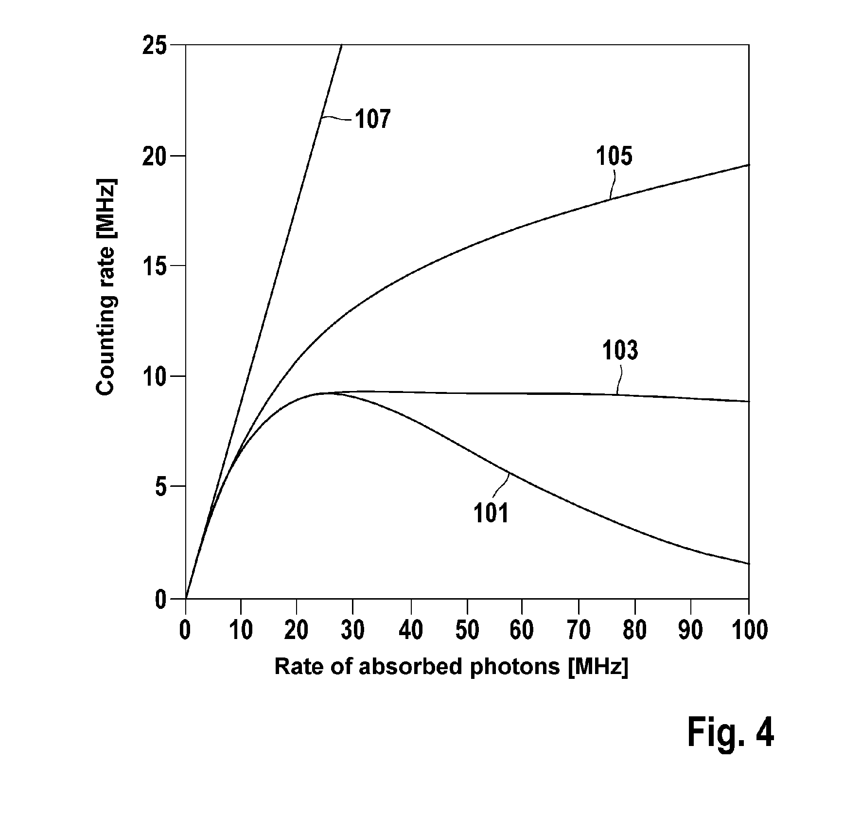
[0007]It has been observed that certain photon-sensitive elements such as SPADs, for example, after the impingement of a photon, cannot be activated anew for a certain dead time, which can be in the range of 1 to 100 ns, for example. In this context, this is also referred to as a paralyzable response behavior. As illustrated schematically for example in FIG. 4 (see curve 101), the counting rate determined by an individual SPAD, at a low rate of absorbed photons, can be approximately proportional to the photon absorption rate. However, the counting rate can start to saturate at a photon absorption rate of somewhat less than the inverse dead time 1 / τ of the SPAD. At even higher photon absorption rates, the counting rate can even decrease, since, at such high photon absorption r...


PUM


Abstract

A photon detector is disclosed that includes, in addition to an immobilisable photon-sensitive element, a photon transmission element. The photon detector is configured such that it can vary photon intensities impacting upon the photon-sensitive element and transmitted by the photon transmission element, for example, by modifying an absorption property or a defocussing property of the photon transmission element. Also, the immobile photon-sensitive element, which can be, for example a SPAD (Single Photon Avalanche Diode), always operates close to the optimal operating range and below an immobilisation range. A distancing device that includes this type of photo detector is also disclosed.

Description

FIELD OF THE INVENTION[0001]The invention relates to a photon detector comprising at least one paralyzable photon-sensitive element, wherein the photon-sensitive element can be embodied for example with an SPAD (Single Photon Avalanche Diode). Furthermore, the invention relates to a distance measuring device comprising such a photon detector.BACKGROUND OF THE INVENTION[0002]Distance measuring devices are known which align a temporally modulated light beam in a direction toward a target object whose distance from the measuring device is intended to be determined, and at least partly detect the light reflected or backscattered from the target object aimed at and use it for determining the distance to be measured. In this case, a typical measurement range is in a range of distances of from a few centimeters up to several hundred meters.[0003]In order to be able to measure the distance from the target object, a propagation time of photons which are emitted from the measuring device towa...

Claims


Application Information

Patent Timeline
IPC IPC(8): G01J1/44G01S17/10
CPCG01J1/04G01J1/0403G01J1/0411G01J1/0418G01J1/0437G01J1/0448G02F2203/52G01J1/42G01S7/4816G01S7/489G01S7/497G01S17/10G01J1/22
Inventor EISELE, ANDREASWOLST, OLIVERSCHMIDTKE, BERND
Owner ROBERT BOSCH GMBH
Learn More