Beam Blanker for Interrupting a Beam of Charged Particles

a beam blanker and charged particle technology, applied in the direction of beam deviation/focusing by electric/magnetic means, instruments, therapy, etc., can solve the problems of affecting the brightness of the beam, and affecting the alignment of the beam,

Active Publication Date: 2012-10-18
FEI CO
View PDF1 Cites 21 Cited by
  • Summary
  • Abstract
  • Description
  • Claims
  • Application Information

AI Technical Summary

Benefits of technology

[0028]For some uses it is necessary to tune frequency and / or phase of the resonant frequency f. This may be achieved by, for example, mechanical tuning means (e.g. a tuning screw), by electronic means (e.g. a phase shifter or a varicap), or in another way (such as the magnetic tuning used in RF isolators / circulators.It is noted that the latter (the RF isolator / circulator) may also ease the demands on impedance matching to the resonant structure as little energy is reflected back into the circuitry generating the driving signal.
[0031]In a particle-optical instrument such as a Scanning Electron Microscope (SEM) or a Transmission Electron Microscope (TEM), or an instrument equipped with a SEM and / or a TEM column, the electron source is often a Schottky emitter. The Schottky emitter typically has an emitting diameter of approximately 20 nm, and a cross-over of less than 20 nm is formed by the condenser optics. An aperture of 100 μm, preferably less than 10 μm, and most preferably less than 1 μm can thus be well used to transmit the beam. It is noted that a smaller aperture implies that the beam is blanked at a lower electric field (a smaller deflection), but that too small an aperture implies problematic alignment. However, an alignment of less than 1 μm is well achievable.

Problems solved by technology

A problem of a pulsed electron source of the type used by Zewail is that it shows a brightness that is much lower than the brightness of the well-known Schottky emitters routinely used in TEMs.
This is difficult to achieve.
It is noted that a smaller aperture implies that the beam is blanked at a lower electric field (a smaller deflection), but that too small an aperture implies problematic alignment.

Method used


Image

  • Beam Blanker for Interrupting a Beam of Charged Particles
  • Beam Blanker for Interrupting a Beam of Charged Particles
  • Beam Blanker for Interrupting a Beam of Charged Particles

Examples


Embodiment Construction

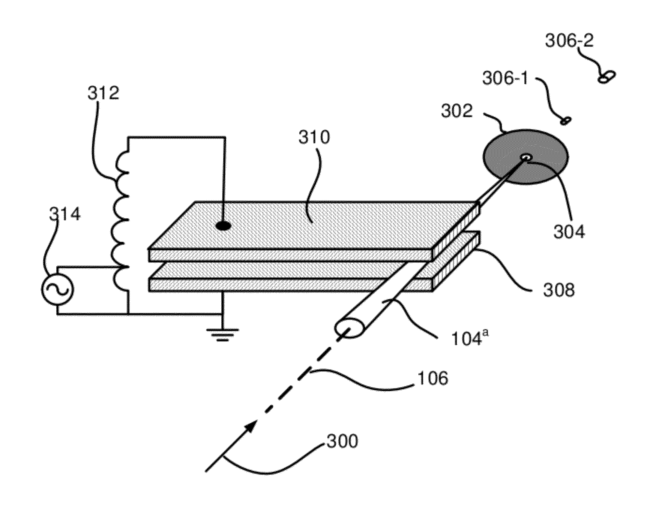
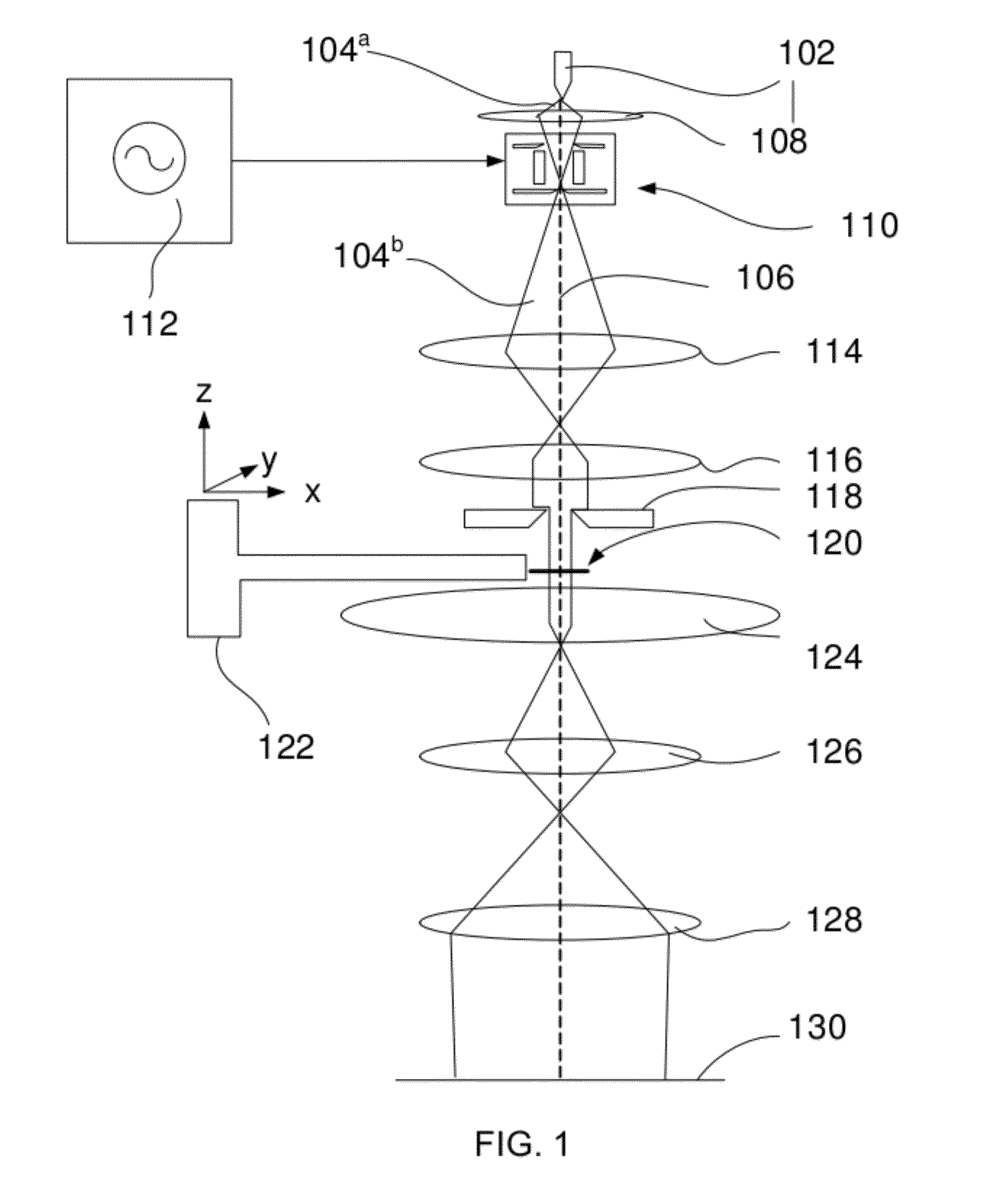
[0040]FIG. 1 schematically shows a TEM equipped with a beam blanker according to the invention.

[0041]A source of charged particles in the form of electron source 102 emits a beam of electrons 104a round electron-optical axis 106. An electron-optical lens 108, in the form of a magnetic or an electrostatic lens, focuses the beam in the beam blanker 110. A signal generator 112 is connected to the beam blanker to provide a driving signal to the beam blanker. The beam 104b leaving the beam blanker enters two condenser lenses 114 and 116, and the opening angle of the beam is limited by beam limiting aperture 118. Thereafter the beam illuminates the electron transparent sample 120. The sample is mounted on a sample holder 122 that may shift or tilt the sample. The so-called objective lens 124 forms a first magnified image of the sample, that is further magnified by lenses 126 and 128 to form an image on image plane 130. The image plane may coincide with a fluorescent screen, a CCD camera o...


PUM


Abstract

The invention relates to an electrostatic beam blanker for a particle-optical apparatus, in which the blanker is used to generate a train of pulses with a fixed repetition rate. Such pulse trains with a sub-picosecond pulse length are for example used in the study of chemistry in the femtosecond scale.The beam blanker according to the invention uses a resonant structure, as a result of which the voltage is amplified by the quality factor Q of the resonant structure. During each zero-crossing of the signal, thus twice per period of the resonant frequency, the beam is transmitted, and the beam is blanked during the rest of the time. In a preferred embodiment the resonant structure comprises a transmission line. Impedance matching of signal source and resonant structure may be performed by tuning stubs.

Description

[0001]This Application claims priority from U.S. Provisional Application 61 / 390,729, filed Oct. 7, 2010, which is hereby incorporated by reference.BACKGROUND AND SUMMARY[0002]The invention relates to a beam blanker for interrupting a beam of charged particles, the beam blanker showing an axis along which charged particles propagate before entering the beam blanker, the beam blanker comprising means for generating an electric field perpendicular to said axis, the electric field for deflecting the charged particles, and an aperture in a diaphragm, the aperture transmitting the beam when the beam is not interrupted and the diaphragm stopping the beam when the beam is interrupted.[0003]Such a beam blanker is known from U.S. Pat. No. 4,445,041.[0004]Beam blanking is used in for example charged particle instruments, such as Scanning Electron Microscopes, Transmission Electron Microscopes, Focused Ion Beam machines, and the like.[0005]A well-known application is the use of a beam blanker f...

Claims


Application Information

Patent Timeline
Patent Type & Authority Applications(United States)
IPC IPC(8): H01J3/26
CPCH01J37/045H01J2237/0432
Inventor KNIPPELS, GUIDO MARTINUS HENRICUSKIEWIET, FREDERICUS BERNARDUSSLINGERLAND, HENDRIK NICOLAASKRUIT, PIETERCOOK, BENJAMIN JOHNNONHEBEL, JACQUES
Owner FEI CO
Why Eureka
Try Eureka