Multi-phase resonant converter

a multi-phase resonant converter and power converter technology, applied in the direction of electric variable regulation, process and machine control, instruments, etc., can solve the problems of generating high-frequency electrical noise, inefficient linear regulators, and generally more complex smpss, so as to reduce the size of electromagnetic interference filters, reduce input ripples, and eliminate output ripples

Active Publication Date: 2012-10-18
MYPAQ HLDG LTD
View PDF11 Cites 87 Cited by
  • Summary
  • Abstract
  • Description
  • Claims
  • Application Information

AI Technical Summary

Benefits of technology

[0016]Reducing the input ripple by such a large factor substantially reduces the size of the electromagnetic interference (EMI) filters. Eliminating the output ripple both reduces EMI, and significantly reduces the ripple current in the bulk capacitor at the output of the converter.
[0017]In some embodiments, the transformers for the multiple interleaved po

Problems solved by technology

The linear regulator tend to be inefficient.
Disadvantages include the fact that SMPSs are generally more complex than linear power supplies, generate high-frequency electrical noise that may need to be carefully suppressed, and have a characteristic ripple voltage at the switching frequency.
However, use of each of these techniques comes with specific drawbacks.
Use of large filters adds space and cost.
Reduction of switching frequency increases the size of passive components and cost.
Reduction of switching speeds reduces efficiency.
However, the interleaving of these converters only yields approximately a factor of 4 decrease in the ripple at the input of the converter.
On the other hand, due to the tolerance of componen

Method used


Image

  • Multi-phase resonant converter
  • Multi-phase resonant converter
  • Multi-phase resonant converter

Examples


Embodiment Construction

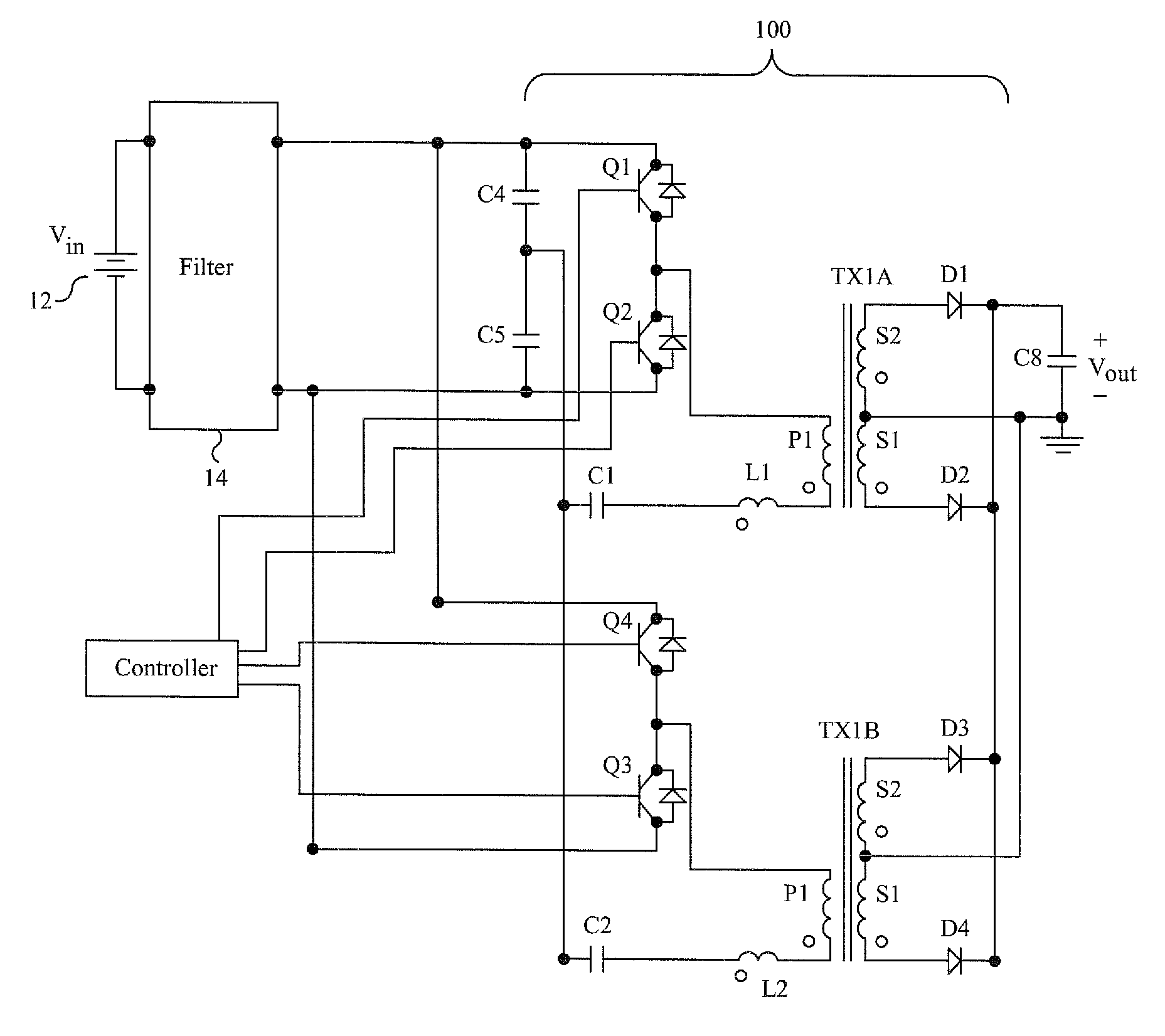
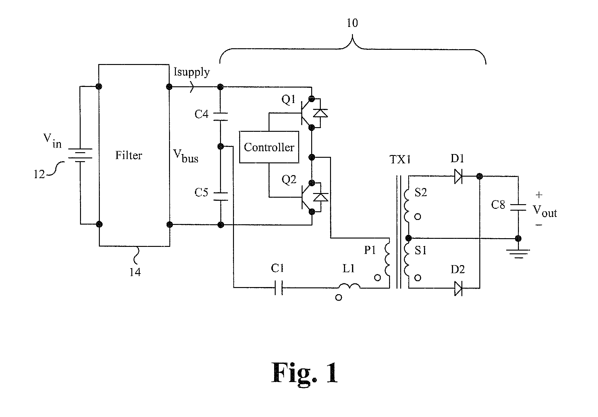
[0034]Embodiments of the power converter are directed to a multi-phase quasi-resonant power converter. Those of ordinary skill in the art will realize that the following detailed description of the power converter is illustrative only and is not intended to be in any way limiting. Other embodiments of the power converter will readily suggest themselves to such skilled persons having the benefit of this disclosure.

[0035]Reference will now be made in detail to implementations of the power converter as illustrated in the accompanying drawings. The same reference indicators will be used throughout the drawings and the following detailed description to refer to the same or like parts. In the interest of clarity, not all of the routine features of the implementations described herein are shown and described. It will, of course, be appreciated that in the development of any such actual implementation, numerous implementation-specific decisions must be made in order to achieve the developer...


PUM


Abstract

A resonant power converter draws current from a source that provides a supply current. Multiple quasi-resonant converters are interleaved and each quasi-resonant converter receives the supply current and forms a phase-shifted current according to drive signals supplied by a controller. Each phase-shifted current includes a dead-time delay and is phase-shifted relative to the other phase-shifted currents. The dead-time delay is determined as a time value within a calculated dead-time delay range having a dead-time delay minimum and a dead-time delay maximum. The outputs of each quasi-resonant converter are added together thereby reducing the AC components of current. Two, three, or four quasi-resonant power converters can be interleaved, each forming phase-shifted currents that are phase-shifted relative to the other phase-shifted currents.

Description

FIELD OF THE INVENTION[0001]The invention relates to power converters. More particularly, the invention relates to a multi-phase resonant power converter configured to reduce high-frequency ripple.BACKGROUND OF THE INVENTION[0002]A power supply is a device or system that supplies electrical or other types of energy to an output load or group of loads. The term power supply can refer to a main power distribution system and other primary or secondary sources of energy. Power conversion refers to the conversion of one form of electrical power to another desired form and voltage, for example converting 115 or 230 volt alternating current (AC) supplied by a utility company to a regulated lower voltage direct current (DC) for electronic devices, referred to as AC-to-DC power conversion.[0003]A switched-mode power supply, switching-mode power supply or SMPS, is a power supply that incorporates a switching regulator. While a linear regulator uses a transistor biased in its active region to ...

Claims


Application Information

Patent Timeline
IPC IPC(8): H02M3/337H02M3/335
CPCH02M3/285Y02B70/1441Y02B70/1491H02M2001/0058Y02B70/10Y02P80/10H02M1/0058H02M3/33573H02M3/33571H02M3/01
Inventor JUNGREIS, AARONBRINLEE, ANTONYGARRITY, PAUL
Owner MYPAQ HLDG LTD
Why Eureka
Try Eureka