
System and Method for Processing Reactor Polymerization Effluent

a reactor and effluent technology, applied in the direction of separation processes, chemical/physical/physicochemical processes, dispersed particle separation, etc., can solve the problems of insufficient control parameters, equipment and energy costs associated with feedstock purification, and significant proportion of the total cost of production of polymers

Active Publication Date: 2012-10-18
CHEVRON PHILLIPS CHEMICAL CO LP
View PDF0 Cites 13 Cited by
  • Summary
  • Abstract
  • Description
  • Claims
  • Application Information

AI Technical Summary

Problems solved by technology

As such, the equipment and energy costs associated with feedstock purification represent a significant proportion of the total cost for the production of such polymers.
Further, the infrastructure required for producing, maintaining, and recycling high purity feedstock represents a significant portion of the associated cost.
Further, such conventional attempts to recover feedstock components have not enabled sufficient control parameters to prevent and / or control deleterious plant conditions.
The drawbacks of these designs can lead to process delays, increased costs, and / or other inefficiencies.

Method used


Image

  • System and Method for Processing Reactor Polymerization Effluent
  • System and Method for Processing Reactor Polymerization Effluent
  • System and Method for Processing Reactor Polymerization Effluent

Examples


##ic example 1

Prophetic Example 1

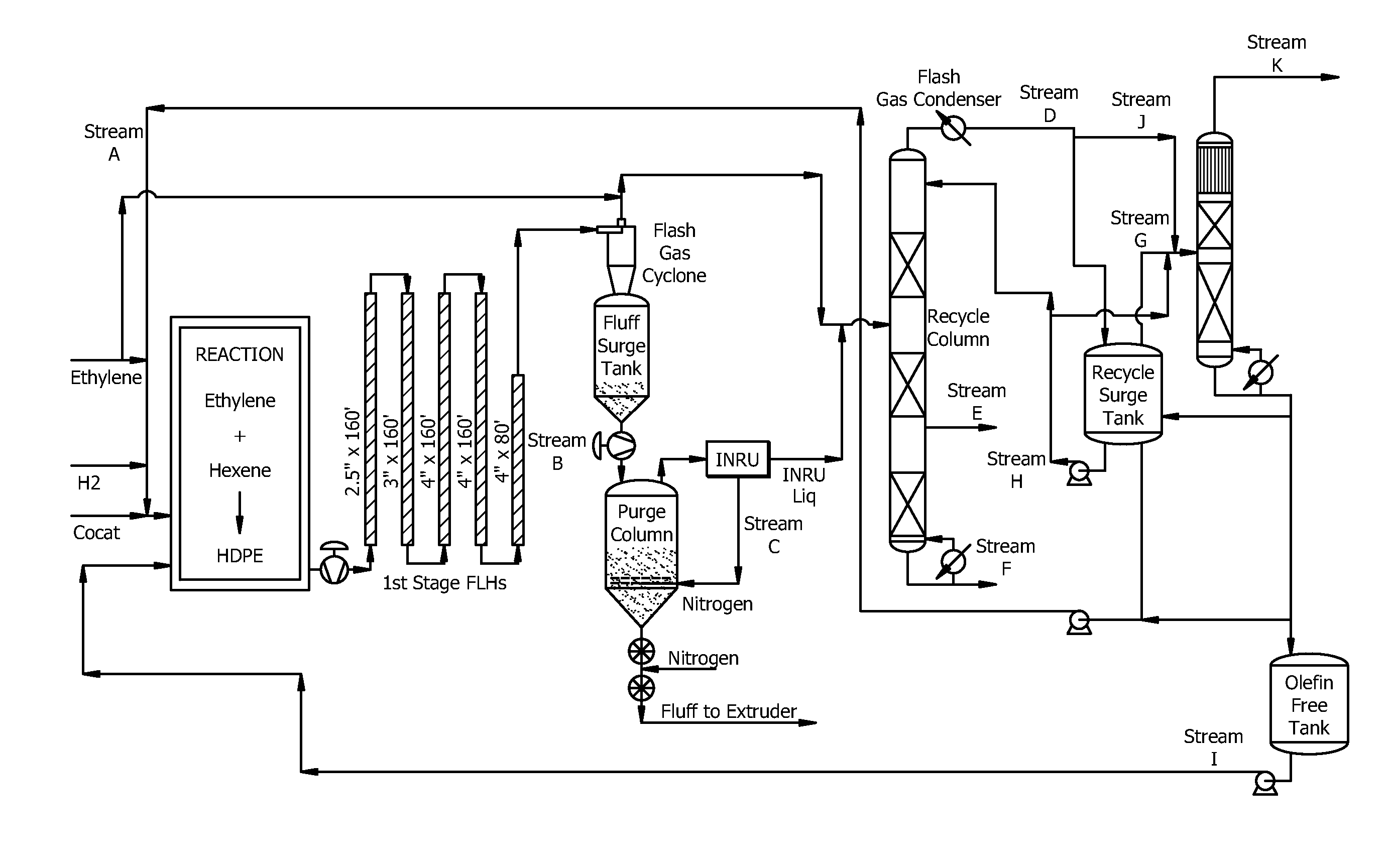
[0082]To demonstrate the operation of the systems and / or processes disclosed herein, a computerized commercial process simulator was employed to generate an output from a model in accordance with the systems and / or processes disclosed herein. The model employed is illustrated at FIG. 3. In the model of FIG. 3, the simulation begins with the introduction of a gaseous stream (for example, like the purified feed stream disclosed herein). The output generated by the commercial process simulator is a material balance and a heat balance, shown in Table 1, below. The names designating the various streams listed in Table 1 correspond to streams illustrated in FIG. 3.

TABLE 1wt %ABCDEFGHIJKHydrogen0.010%0.087%0.087%0.07%——1.22%0.00%0.0%—5.9%Nitrogen0.006%0.006%0.198%0.02%——0.36%0.00%0.00%—1.7%Ethylene2.092%3.006%3.001%2.98%——15.64%2.00%0.00%—74.9%Ethane0.195%0.264%0.264%0.26%——1.07%0.00%0.00%—5.1%Propane0.000%0.000%0.000%0.00%——0.00%0.00%0.00%0.0%0.0%Butene1.406%1.429%1.426...

embodiment a

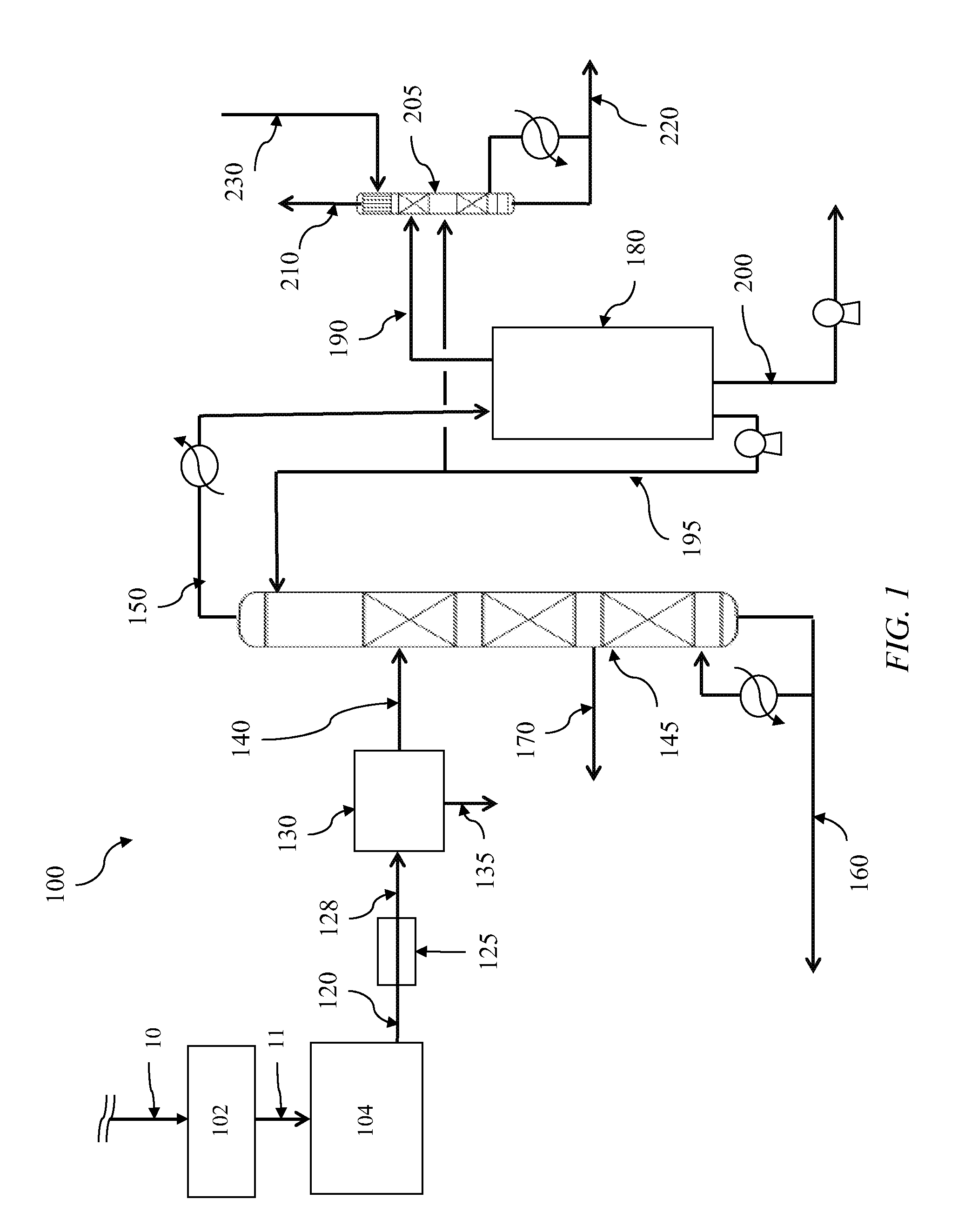
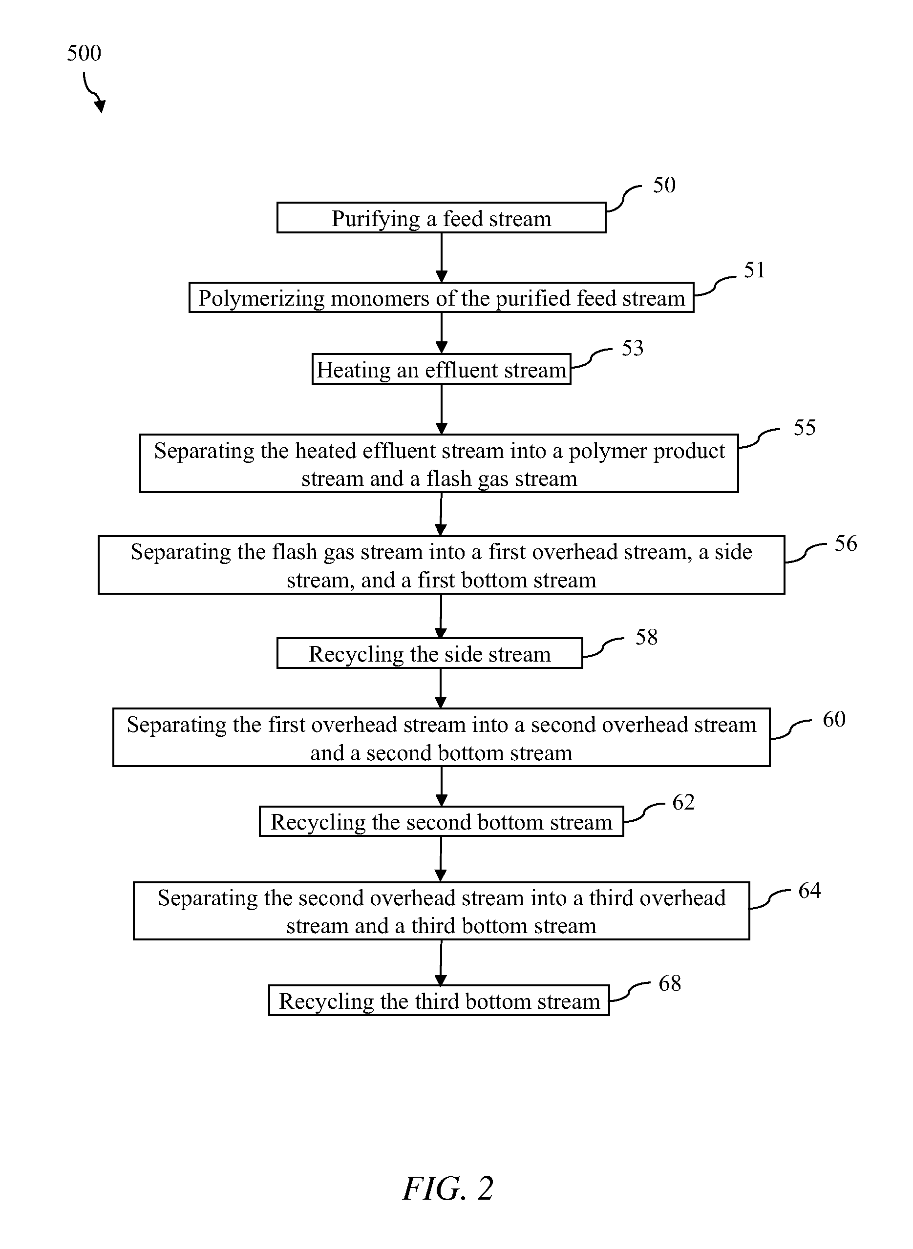
[0084]A method of treating a polymerization reactor effluent stream comprising:

[0085]recovering the reactor effluent stream from the polymerization reactor;

[0086]flashing the reactor effluent stream to form a flash gas stream;

[0087]separating the flash gas stream into a first top stream, a first bottom stream, and a side stream, wherein the side stream substantially comprises hexene;

[0088]separating the first top stream into a second top stream and a second bottom stream, wherein the second bottom stream substantially comprises isobutane; and

[0089]separating the second top stream into a third top stream and a third bottom stream, wherein the third top stream substantially comprises ethylene, and wherein the third bottom stream is substantially free of olefins.

embodiment b

[0090]The method of Embodiment A, further comprising returning at least a portion of the side stream to the polymerization reactor.


PUM

PropertyMeasurementUnit
Fractionaaaaaaaaaa
Fractionaaaaaaaaaa
Percent by massaaaaaaaaaa

Abstract

A method of treating a polymerization reactor effluent stream comprising recovering the reactor effluent stream from the polymerization reactor, flashing the reactor effluent stream to form a flash gas stream, separating the flash gas stream into a first top stream, a first bottom stream, and a side stream, wherein the side stream substantially comprises hexane, separating the first top stream into a second top stream and a second bottom stream, wherein the second bottom stream substantially comprises isobutene, and separating the second top stream into a third top stream and a third bottom stream; wherein the third top stream substantially comprises ethylene, and wherein the third bottom stream is substantially free of olefins.

Description

CROSS-REFERENCE TO RELATED APPLICATIONS[0001]Not Applicable.FIELD OF THE INVENTION[0002]This disclosure generally relates to a system for processing an effluent stream from a polymerization reaction process. Particularly, the disclosure relates to removing one or more undesired components and recycling one or more reusable components from a polymerization reaction effluent stream.BACKGROUND OF THE INVENTION[0003]The production of polymers such as polyethylene requires a high purity feedstock of various components, including monomers and co-monomers. In order to offset some of the costs and maximize production, it can be useful to reclaim and / or recycle some feedstock components from an effluent stream resulting from the polymerization reaction. To accomplish this, the reclaimed effluent streams have conventionally either been routed through a purification process or redirected through other redundant processing steps.[0004]Conventional attempts to industrially produce high purity fe...

Claims


Application Information

Patent Timeline
IPC IPC(8): C08F6/00
CPCB01D3/009B01D19/0036B01J19/242C08F210/16B01D45/02B01D3/06B01J19/0053C08F6/001C08J11/02C08F2/00C08F2/01C08L23/0815
Inventor MILLS, ANDREW J.ROMIG, RALPH W.LOH, JI XIAN X.
Owner CHEVRON PHILLIPS CHEMICAL CO LP
Learn More