

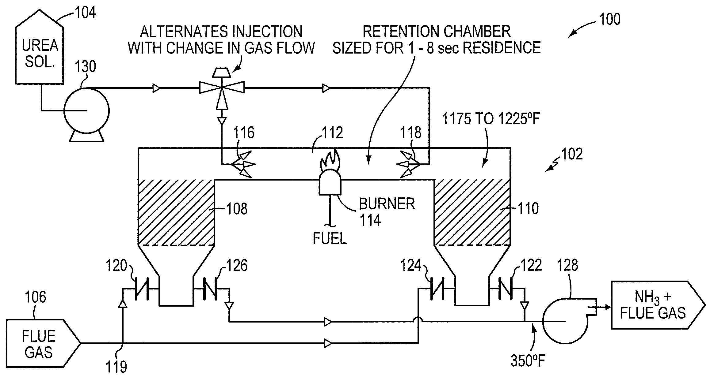
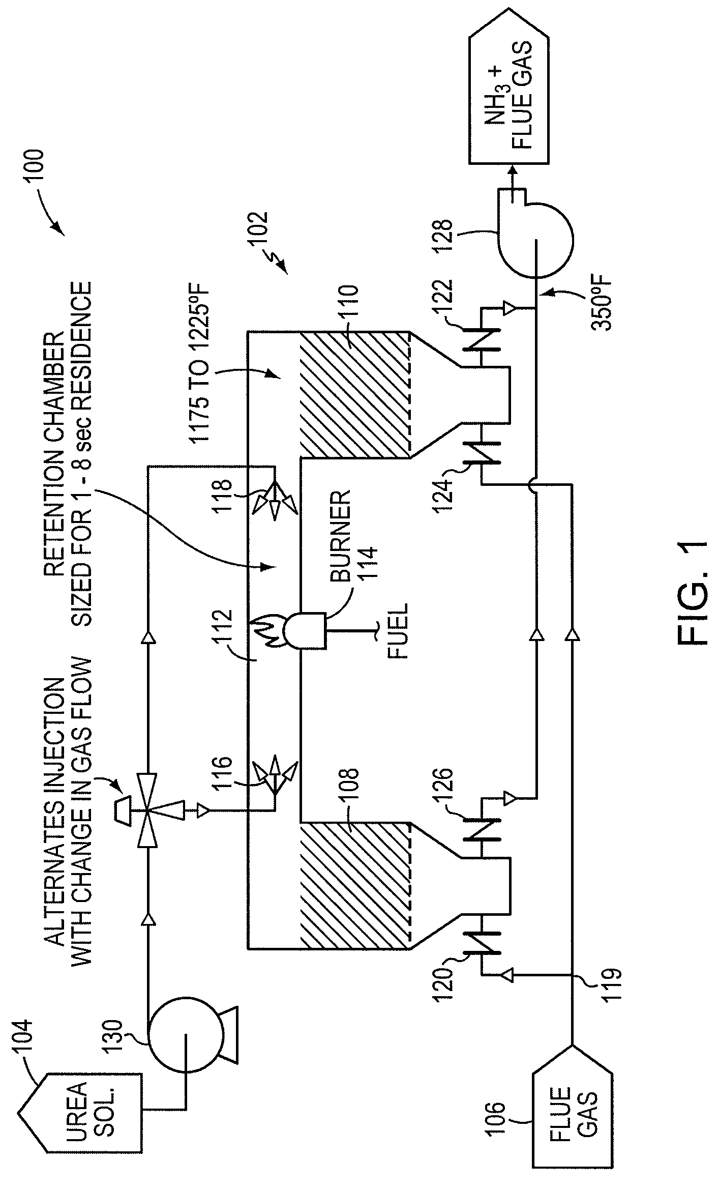
Thermal decomposition of urea in a side stream of combustion flue gas using a regenerative heat exchanger
a heat exchanger and side stream technology, applied in the direction of machines/engines, lighting and heating apparatus, separation processes, etc., can solve the problems of inefficiency, inefficiency, direct use of ammonia in these processes, and burner consumption of fuel, so as to improve thermal efficiency and conserve heat produced by the burner
- Summary
- Abstract
- Description
- Claims
- Application Information
AI Technical Summary
Benefits of technology
Problems solved by technology
Method used
Image

Examples
Embodiment Construction
[0027]As used herein, a “combustor” is understood to include any unit, system, or apparatus which combusts one or more carbonaceous fuels to provide heat, e.g., for direct or indirect conversion to mechanical or electrical energy. Carbonaceous fuels include the hydrocarbons normally used as fuels, as well as combustible waste materials such as municipal solid waste, industrial process waste, and the like. Burners and furnaces, as well as internal combustion engines of the Otto, Diesel, and turbine types, are included within the term “combustor” and can benefit from the invention. Large-scale combustors are considered as most benefiting from the invention, although stationary and mobile combustors of all types are contemplated as well.
[0028]As used herein, “flue gas” is understood to mean any gas exhausted from, or generated by operation of, a combustor, or part of a combustor. In general, a large-scale combustor burns fuel with the resulting production of flue gas containing nitroge...
PUM
| Property | Measurement | Unit |
|---|---|---|
| temperature | aaaaa | aaaaa |
| temperature | aaaaa | aaaaa |
| temperature | aaaaa | aaaaa |
Abstract
Description
Claims
Application Information