Spring leaf and overrunning clutch provided with the same

a technology of overrunning clutch and spring leaf, which is applied in the direction of clutches, mechanical actuated clutches, freewheel clutches, etc., can solve the problems of detachment displacement failure of spring leaf, structure deficiency, and difficulty in manufacturing the needle roller stand of the structure, etc., to achieve relatively stable elasticity received by the needle roller, simple structure, and convenient fabrication and installation

Active Publication Date: 2012-11-08
JIANG SU NAN FANG BEARING CO LTD
View PDF3 Cites 2 Cited by
  • Summary
  • Abstract
  • Description
  • Claims
  • Application Information

AI Technical Summary

Benefits of technology

[0009]In a free state, an angle formed between the V-shaped bended part and the straight strip of the clamping strip is slightly smaller than an angle formed between the bottom surface of the mounting groove for the spring leaf and the outer surface of the crossbeam. Generally, the angle formed between the V-shaped bended part and the straight strip of the clamping strip is 5° to 15° smaller than the angle formed between the bottom surface of the mounting groove for the spring leaf and the outer surface of the crossbeam. Through the proper elasticity of the V-shaped bended part, the clamping strip of the spring leaf may be reliably clamped on the retainer.
[0010]The present invention has the following effects. The spring leaf of the present invention has a simple structure, and is convenient to fabricate and install. Through the V-shaped bended part at either end of the clamping strip of the spring leaf clamped on the retainer, the spring leaf may be reliably fixed on the retainer, thereby ensuring that the spring leaf is not deviated from the correct working position in operation under frequent impacts or a centrifugal force. No relative displacement is generated between the spring leaf and the retainer, and correspondingly, the elasticity received by the needle roller is relatively stable. The V-shaped bended part at either end of the spring leaf is fixed on the retainer, thereby providing an axial direction limitation function and preventing the axial direction displacement of the spring leaf. The middle part of the support strip of the spring leaf is the straight segment, either end of which is provided with the arc segment, thus improving the rigidity of the support strip of the spring leaf. The two connection beams are used to connect the clamping strip and the support strip, so that the arc segment at either end of the support strip is individually supported, receives a stable force, and has a large bearing capacity.

Problems solved by technology

The needle roller stand of the structure is difficult to manufacture.
As the spring leaf is only placed in the raised slot of the needle roller hole in the needle roller stand, under the condition of a high rotational speed, there is a risk of detachment displacement failure of the spring leaf.
Likewise, this structure has the deficiency that the retainer is difficult to fabricate.
This spring structure can improve the bearing capability of the spring to some extent, but the elastic clamp at the back end buckles the spring on the crossbeam of the retainer, so that when the rotational speed is high, there is a risk that the elastic clamp may be disengaged from the crossbeam of the retainer under the centrifugal force.
The tail end of the arc spring leaf is formed by punching, and the end surface of the tail end after being bent is in contact with a supported roller at an acute angle, which in use, may easily cause the abrasion of the partial surface of the needle roller and generate noises.
Meanwhile, the tail end of the arc spring leaf may also be easily abraded, which causes insufficient elasticity supported on the needle roller and loses the function of the overrunning clutch.
After a force is applied on the spring leaves, the folded root may be easily broken.
For example, referring to FIGS. 8, 9, and 10, as the spring leaf is suspended on the crossbeam of the retainer, the spring leaf and the retainer may generate a certain displacement in the axial direction, so the elasticity of the spring leaf received by the needle roller in movement is unstable.
Moreover, during the reciprocation of the clutch at a high rotational speed and high frequency, the spring leaf is impacted by the needle roller, which easily causes the displacement and detachment.
In addition, the part of the spring leaf that supports the needle roller in suspension is a bending part formed by punching, and when the spring leaf is under a force in operation, the folded root may be easily broken, resulting in a defective product.
Further, as shown in FIGS. 3, 4, 5, 6, 7, and 12b, the contact position of the spring leaf and the needle roller is located at the middle part of the needle roller instead of being close to the end part, so the force received by the needle roller in movement is uneven, which may easily cause tilting of the needle roller.

Method used


Image

  • Spring leaf and overrunning clutch provided with the same
  • Spring leaf and overrunning clutch provided with the same
  • Spring leaf and overrunning clutch provided with the same

Examples


Embodiment Construction

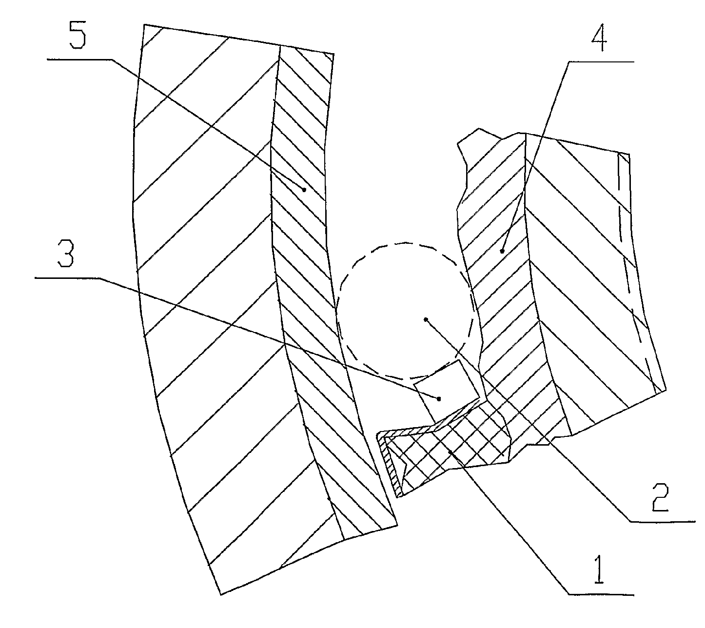
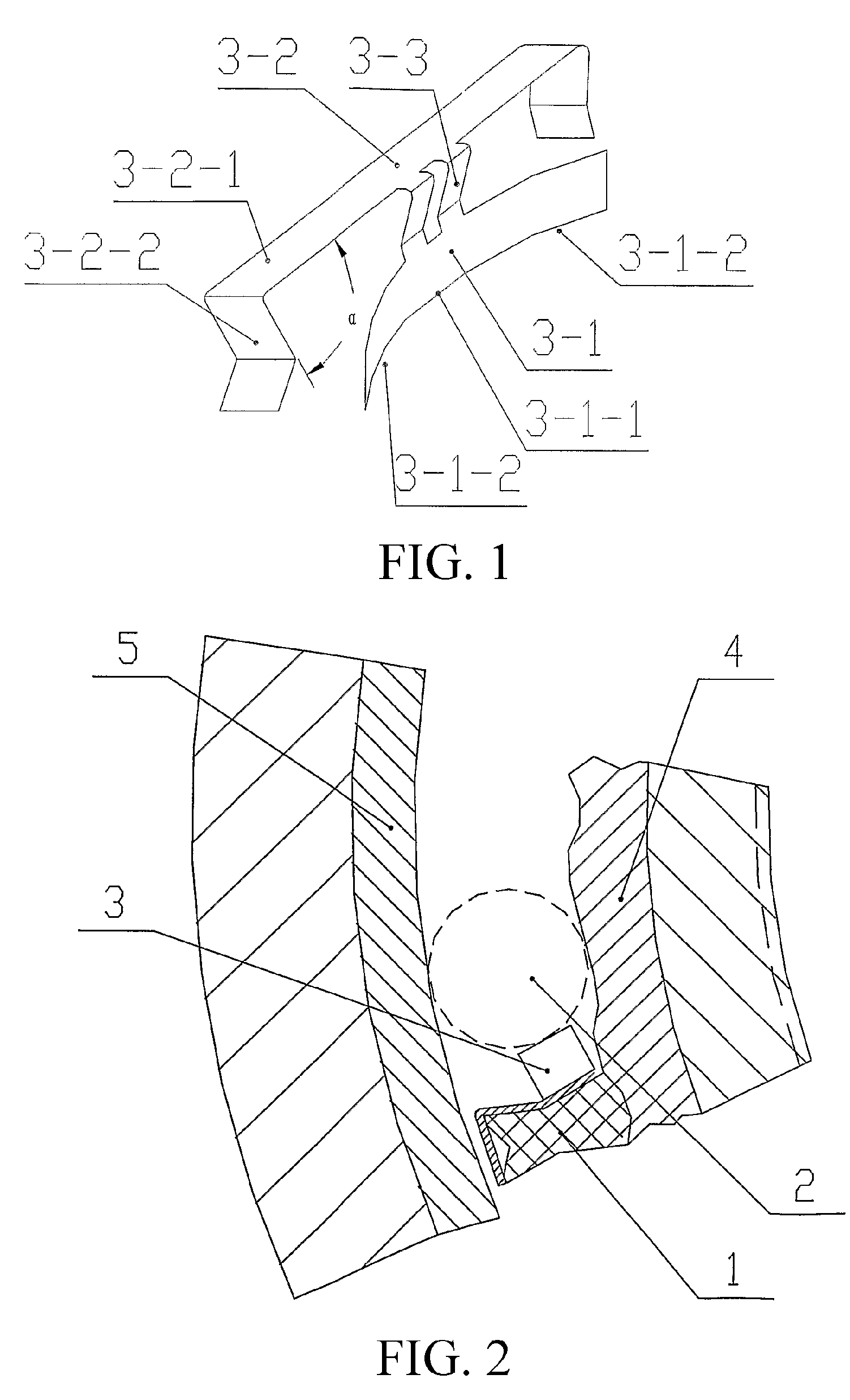
[0019]FIG. 1 illustrates an exemplary embodiment of a spring leaf according to the present invention. The spring leaf is made up of a support strip 3-1, a clamping strip 3-2, and two connection beams 3-3. The support strip 3-1 supports the needle roller 2 in suspension. The connection beams 3-3 connect the support strip 3-1 with the clamping strip 3-2, and are in a flat 7-shape. The main body of the clamping strip 3-2 is a straight strip 3-2-1, either end of which is provided with a V-shaped bended part 3-2-2. A middle part of the support strip 3-1 is a straight segment 3-1-1, either end of which is provided with an arc segment 3-1-2. The straight segment 3-1-1 respectively intersects with the two arc segments 3-1-2. End surfaces of the two arc segments 3-1-2 of the support strip 3-1 support the needle roller 2 in suspension. One end of the connection beam 3-3 is connected to an end surface of the straight strip 3-2-1 of the clamping strip, and the other end of the connection beam 3...


PUM


Abstract

A spring leaf and an overrunning clutch provided with the same are provided. The spring leaf is made up of a support strip (3-1), a clamping strip (3-2), and a connection beam (3-3). The support strip (3-1) supports a needle roller in suspension. The connection beam (3-3) connects the support strip (3-1) with the clamping strip (3-2). The main body of the clamping strip (3-2) is a straight strip (3-2-1), either end of which is provided with a V-shaped bended part (3-2-2). The overrunning clutch is provided with a retainer, multiple needle rollers, and multiple spring leaves. Mounting grooves for the spring leaves are respectively disposed at positions, corresponding to each crossbeam, on outer end surfaces of a first and a second annular end edge at both ends of a window hole of the retainer. The bottom of the mounting groove for the spring leaf is V-shaped when cut along an axial direction of the retainer. An inner surface of the straight strip (3-2-1) of the clamping strip (3-2) of the spring leaf is matched with an outer surface of the crossbeam. An inner surface of the V-shaped bended part (3-2-2) of the clamping strip (3-2) is matched with a bottom surface of the mounting groove for the spring leaf. The technical problem of the potential displacement and detachment of the spring leaf during the reciprocation of the existing overrunning clutch at a high rotational speed and high frequency is solved by the invention.

Description

BACKGROUND OF THE INVENTION[0001]1. Field of Invention[0002]The present invention relates to a spring leaf and an overrunning clutch provided with the same.[0003]2. Related Art[0004]An overrunning clutch is a clutch that automatically engages or disengages when the relative moving speed of a driving part and a follower part changes or the reciprocation direction changes; and is a basic component in the mechanical transmission of Mechanical & Electrical Integration. The major functions of the overrunning clutch are backstopping, accurate positioning, torque transmission, or breaking the torque, so the overrunning clutch is also referred to as a backstop or one-way bearing, which is widely applied in the machine tools, packaging machines, printing machines, light industry machines, textile machines, petrochemical machines, cement machines, metallurgical machines, transportation machines, reducers, and the like. The overrunning clutch has a great varieties, among which the ratchet over...

Claims


Application Information

Patent Timeline
Patent Type & Authority Applications(United States)
IPC IPC(8): F16D41/064
CPCF16D41/067F16D41/064
Inventor ZHOU, XUEGANGXUE, QINGSHI, JIANWEI
Owner JIANG SU NAN FANG BEARING CO LTD
Why Eureka
Try Eureka