METHOD AND APPARATUS FOR TRANSMISSION OF SOUND WAVES WITH HIGH LOCALIZATION of SOUND PRODUCTION

a technology of sound wave transmission and high localization, applied in the direction of transducer casings/cabinets/supports, electrical transducers, frequency/directions obtaining arrangements, etc., can solve the problems of affecting the reception of loudspeakers such as large diameters, and affecting the reception of sound waves. , to achieve the effect of variable intersection location

Inactive Publication Date: 2012-11-08
MARGALIOT MENACHEM
View PDF4 Cites 10 Cited by
  • Summary
  • Abstract
  • Description
  • Claims
  • Application Information

AI Technical Summary

Benefits of technology

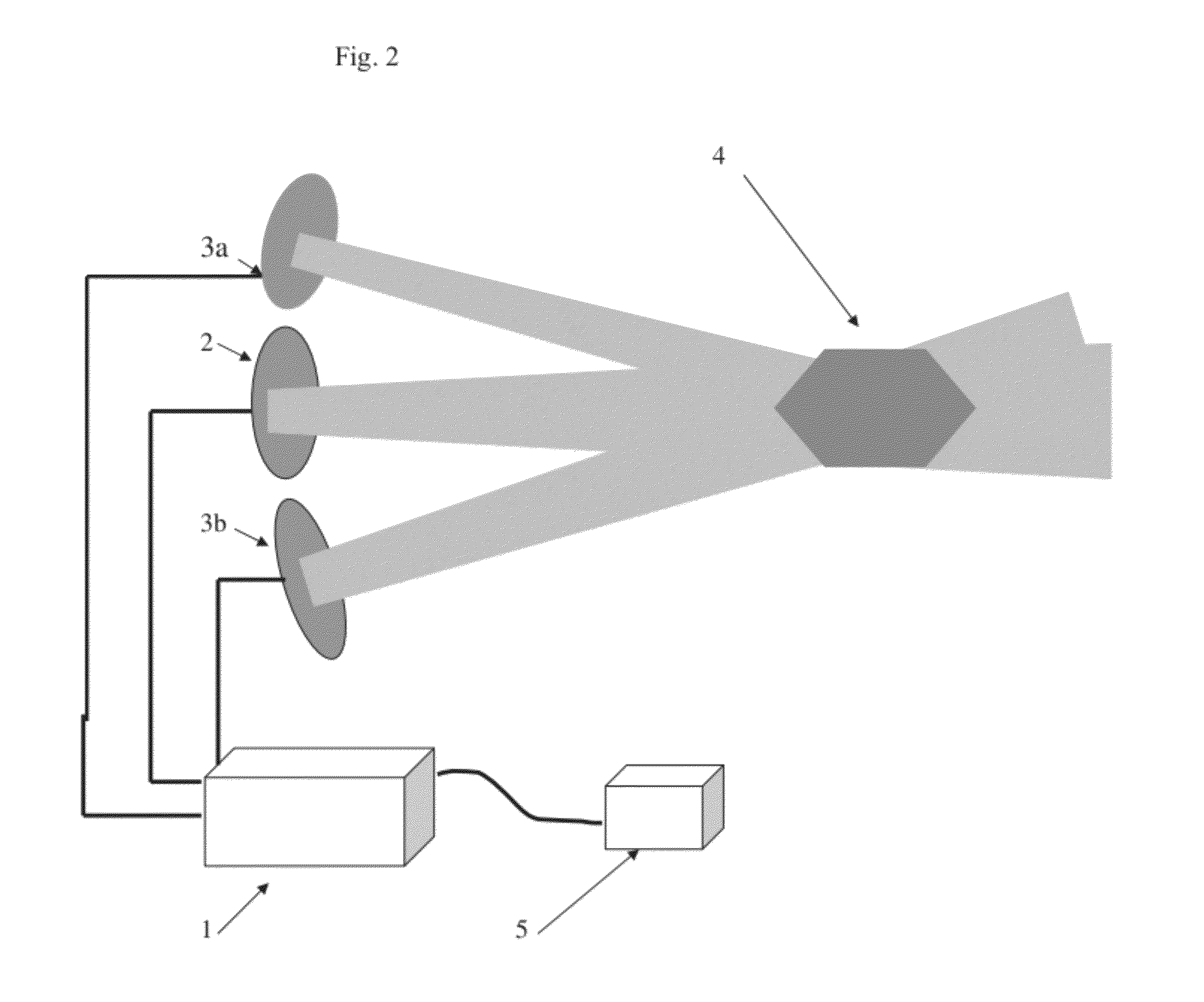
[0018]The system may include devices for positioning the ultrasonic transducers so as to cause the ultrasonic beams thus produced, to intersect at a desired location in space (the audible region), wherein the directing devices are controllable by the operator of the system, thus enabling variations in the intersection location.

Problems solved by technology

However, loudspeakers of such large diameters are impractical.
This method however produces sound all along its path, and as the loss of energy from the ultrasonic beam is non-linear in beam intensity (at higher intensities, relatively more energy is lost), the amplitude modulation becomes distorted along the propagation path.
Another problem with this approach is that the sound is produced all along the beam path, and thus, if it is desired that sound be produced only at a limited region (for example; in the near proximity of a specific listener only), this approach fails.

Method used


Image

  • METHOD AND APPARATUS FOR TRANSMISSION OF SOUND WAVES WITH HIGH LOCALIZATION of SOUND PRODUCTION
  • METHOD AND APPARATUS FOR TRANSMISSION OF SOUND WAVES WITH HIGH LOCALIZATION of SOUND PRODUCTION
  • METHOD AND APPARATUS FOR TRANSMISSION OF SOUND WAVES WITH HIGH LOCALIZATION of SOUND PRODUCTION

Examples


Embodiment Construction

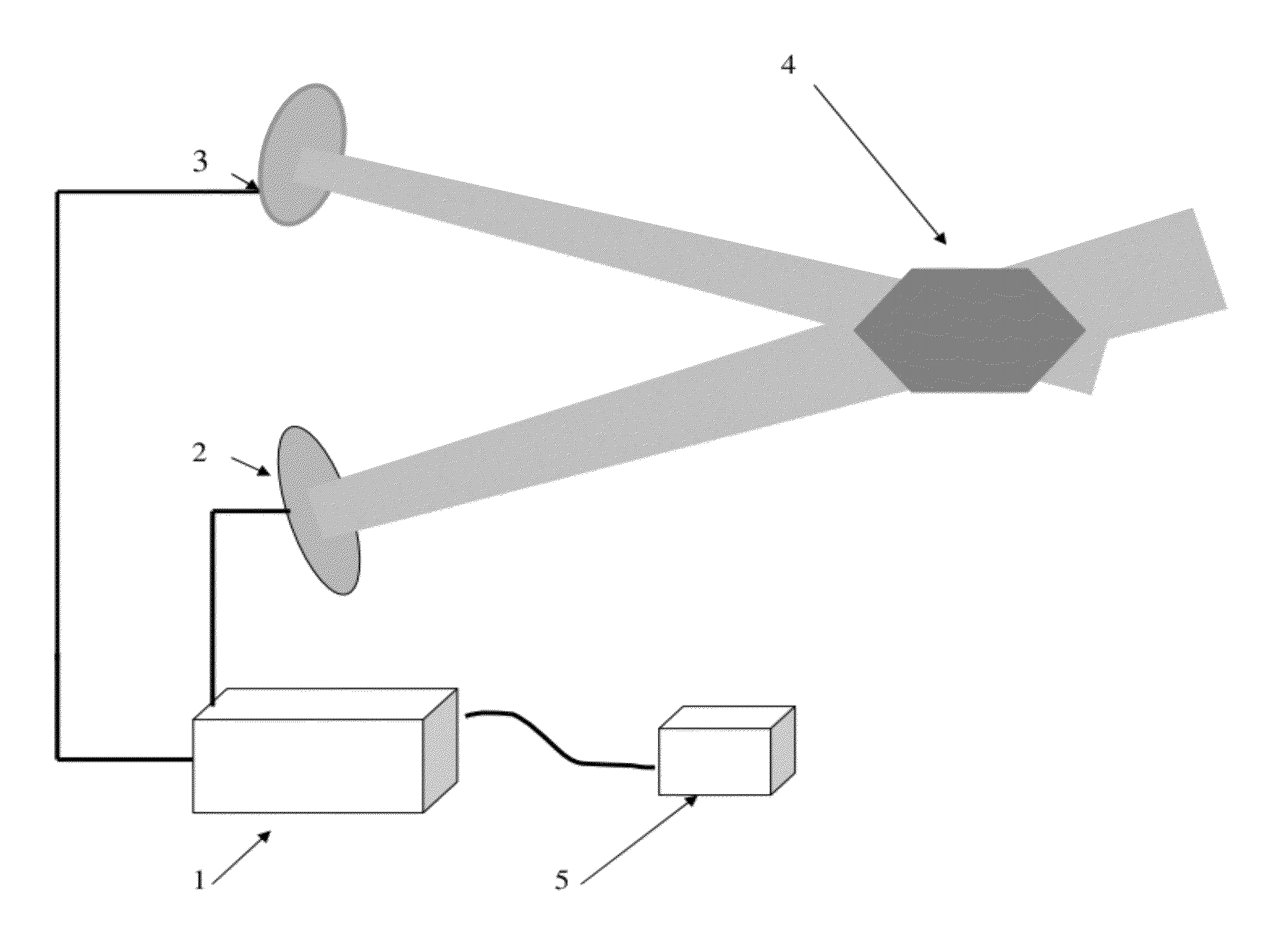
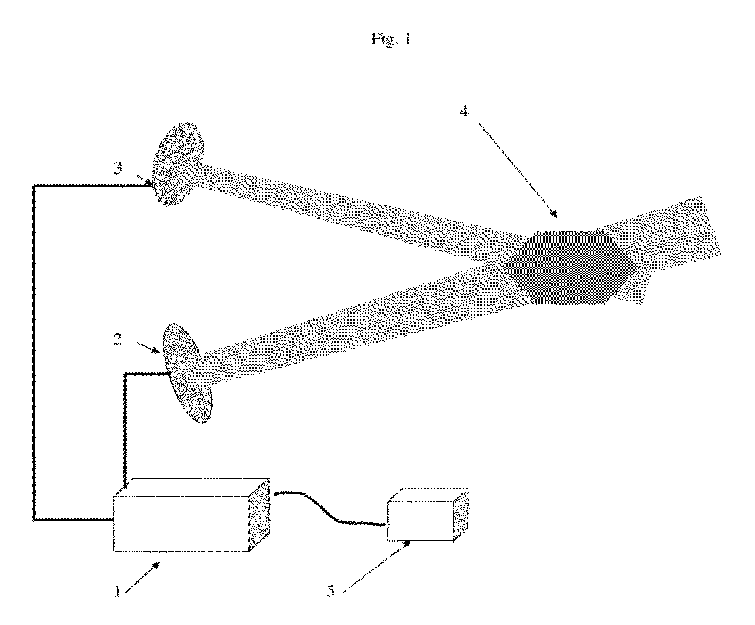
[0028]Reference is now made to FIG. 1, which illustrates a system for the production of directional sound, constructed and operative in accordance with an embodiment of the present invention.

[0029]The directional audio loudspeaker of the present invention may include two (2) ultrasonic emitters. The first of these emits an ultrasonic wave at a fixed frequency, henceforth referred to as the reference frequency (or frequency A).

[0030]The second of these sources emits an ultrasonic wave at the same frequency as the above reference frequency, but its phase is shifted versus the phase of the reference frequency where the frequency of shifting is the desired audio frequency and the magnitude of phase shifting is dependent on the relative intensity of audio signal. The intensity of the waves emitted from these two emitters is set to be equal and controllable by the user.

[0031]Since the ultrasonic waves have a high frequency (well above 20 kHz), their wavelengths are short (in comparison to...


PUM


Abstract

A system for the production of localized audible sound, including a source of voltage oscillations in the ultrasonic frequency range, at a reference frequency. The voltage source is connected to a first ultrasonic transducer, emitting a first beam of ultrasonic waves (the reference beam) in a relatively narrow beam, in a desired direction. The same voltage source is connected to a phase shifter, feeding a second ultrasonic transducer from which an ultrasonic wave is emitted, of the same frequency and intensity as the reference beam, but phase shifted relative to it.

Description

FIELD OF THE INVENTION[0001]The present invention relates generally to the directional transmission of sound waves, producing sonic information in a limited region of space, using small aperture speakers.BACKGROUND OF THE INVENTION[0002]It is a general rule in the physics of wave emission, that when high directionality of a beam of waves is desired, the aperture from which these waves are emitted must be large compared to the wavelength of the waves.[0003]To be more specific: the dispersion angle of a wave beam emitted from a circular aperture of diameter D is given by:θ=2.44λ / D   1)[0004]with θ being the beam dispersion angle (in radians) and λ—the wavelength.[0005]To obtain high directionality (namely: a small θ), for a given wavelength λ, one must thus use a large D source.[0006]With specific regard to sound waves, one must consider a minimal frequency of about 100 Hz (this is the lower frequency limit for most medium quality sound systems).[0007]This acoustic frequency correspon...

Claims


Application Information

Patent Timeline
Patent Type & Authority Applications(United States)
IPC IPC(8): H04R1/40
CPCH04R1/403H04R2217/03H04R3/12
Inventor MARGALIOT, MENACHEM
Owner MARGALIOT MENACHEM
Why Eureka
Try Eureka