Optical Transmission System

a transmission system and optical transmission technology, applied in the field of optical transmission systems, can solve the problems of not equalizing the modulation distortion that is the waveform distortion caused, most of the modulation distortion remains, and can not compensate for a part of the received waveform, so as to prevent the degradation of transmission characteristics, enhance the practicality of the optical transmission system, and equalize the modulation distortion in the optical transmission system

Inactive Publication Date: 2012-11-08
HITACHI LTD
View PDF11 Cites 29 Cited by
  • Summary
  • Abstract
  • Description
  • Claims
  • Application Information

AI Technical Summary

Benefits of technology

[0047]According to the present invention, it is possible to equalize the modulation distortion in the optical transmission system using the direct detection. Accord...

Problems solved by technology

However, only a part of the distortion of the received waveform can be compensated by the linear transversal filters generally used as those adaptive equalizer circuits.
However, in principle, the adaptive equalizer circuits 115-1 and 115-2 cannot equalize the modulation distortion that is the waveform distortion caused by the linear degradation in the interior of the optical transmitter.
In those cases, only a small effect of the adaptive equalization is obtained, an...

Method used


Image

  • Optical Transmission System
  • Optical Transmission System
  • Optical Transmission System

Examples


first embodiment

[0064]FIG. 6 is a configuration diagram of a direct detection optical multilevel transmission system using an optical multilevel phase modulation according to a first embodiment of the present invention.

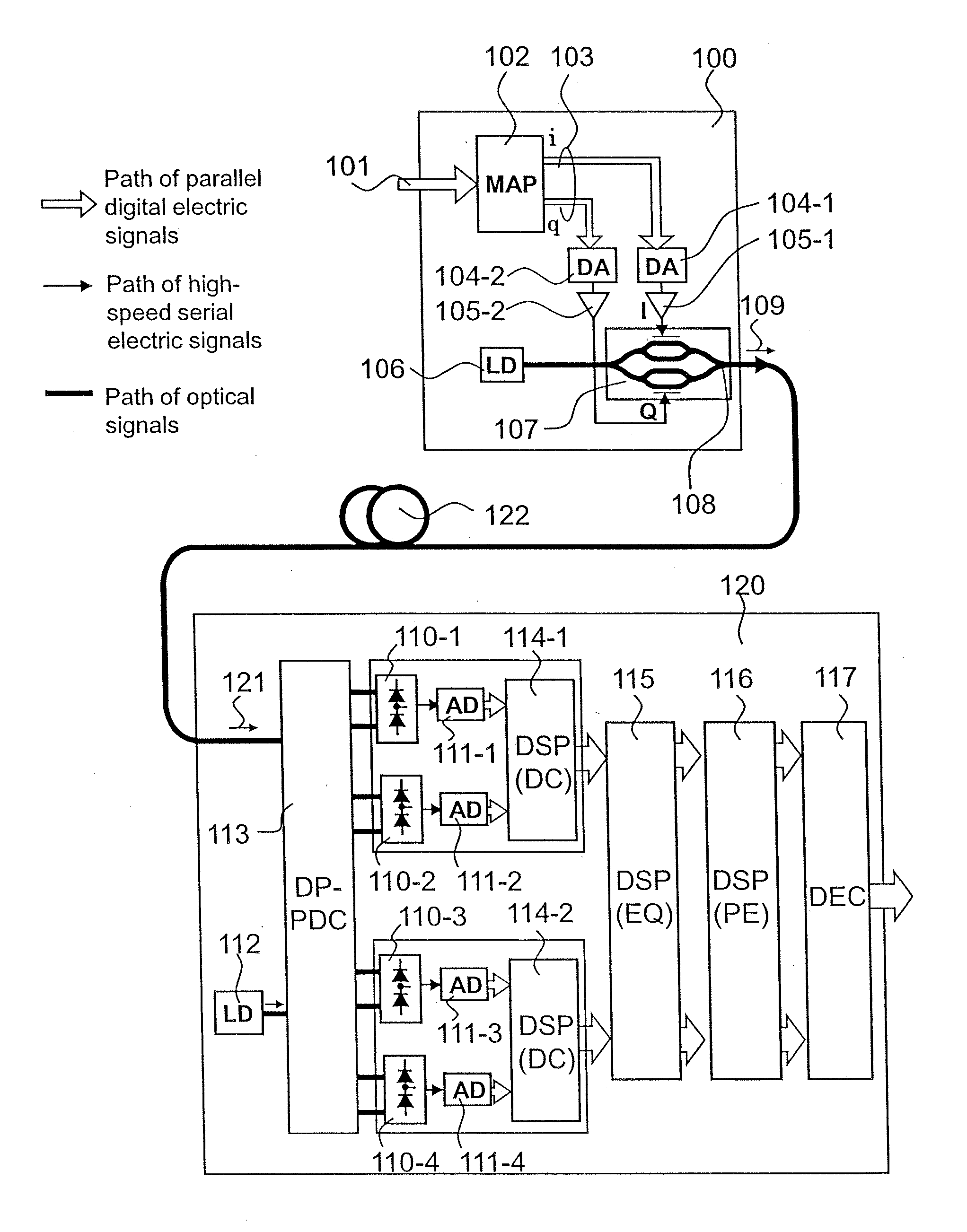
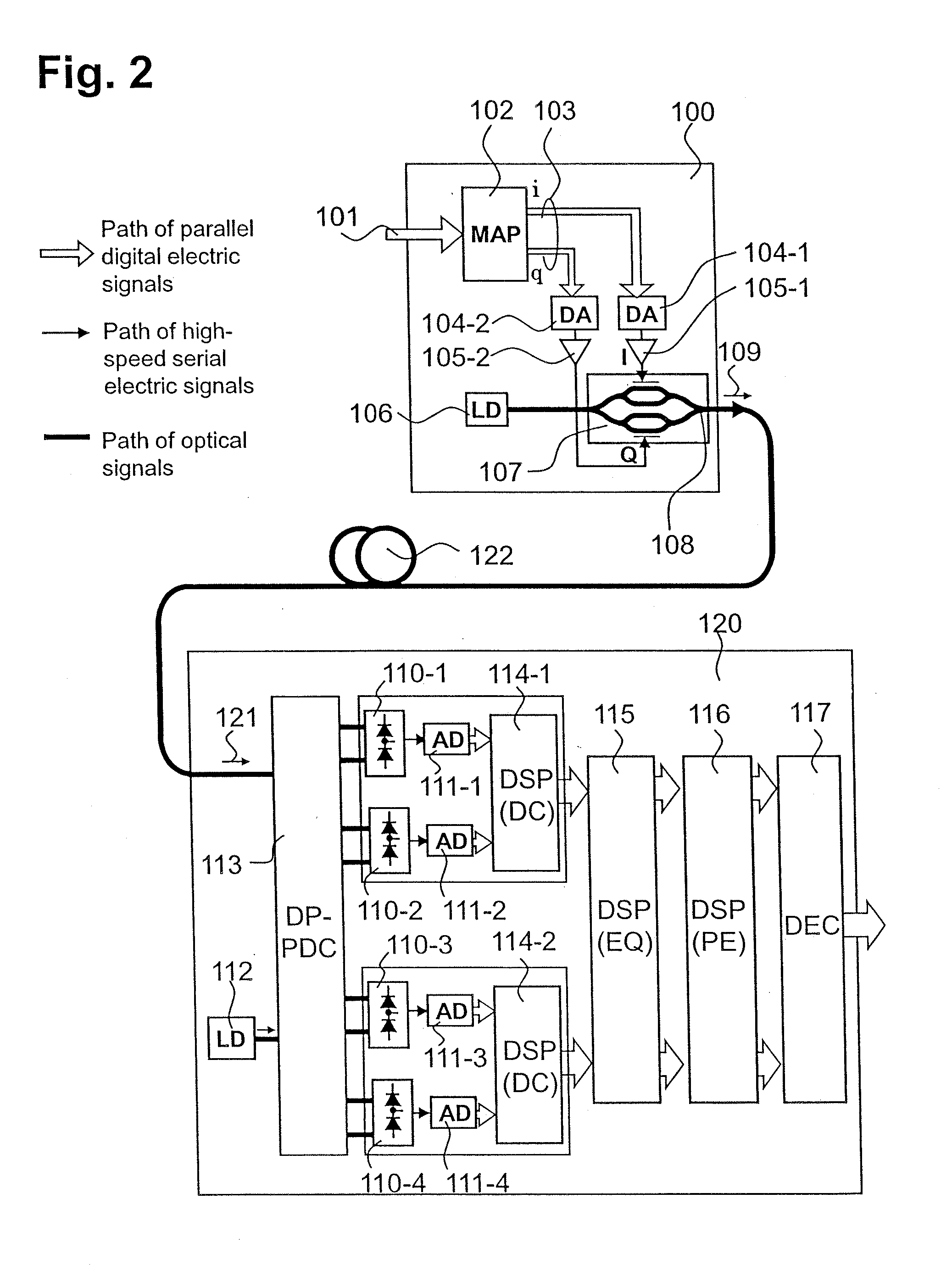
[0065]Features of this configuration resides in that, for example, a pure multilevel phase modulation optical signal is generated by the aid of a polar coordinate based optical phase modulator on a transmitter side, and a differential phase component is extracted from a received signal, and adaptively equalized in a phase area to equalize a modulation distortion. Hereinafter, in this embodiment, a channel of an optical signal is indicated by a heavy line, a channel of a high-frequency signal of electricity is indicated by a thin line, and channels of parallel electric digital signals using plural signal lines are indicated by outline arrows.

[0066]This optical transmission system includes, for example, an optical phase multilevel transmitter (optical transmitter) 200, and an optical p...

second embodiment

[0076]FIG. 9 is a is a configuration diagram of a direct detection optical multilevel transmission system using an optical multilevel amplitude and phase modulation according to a second embodiment of the present invention.

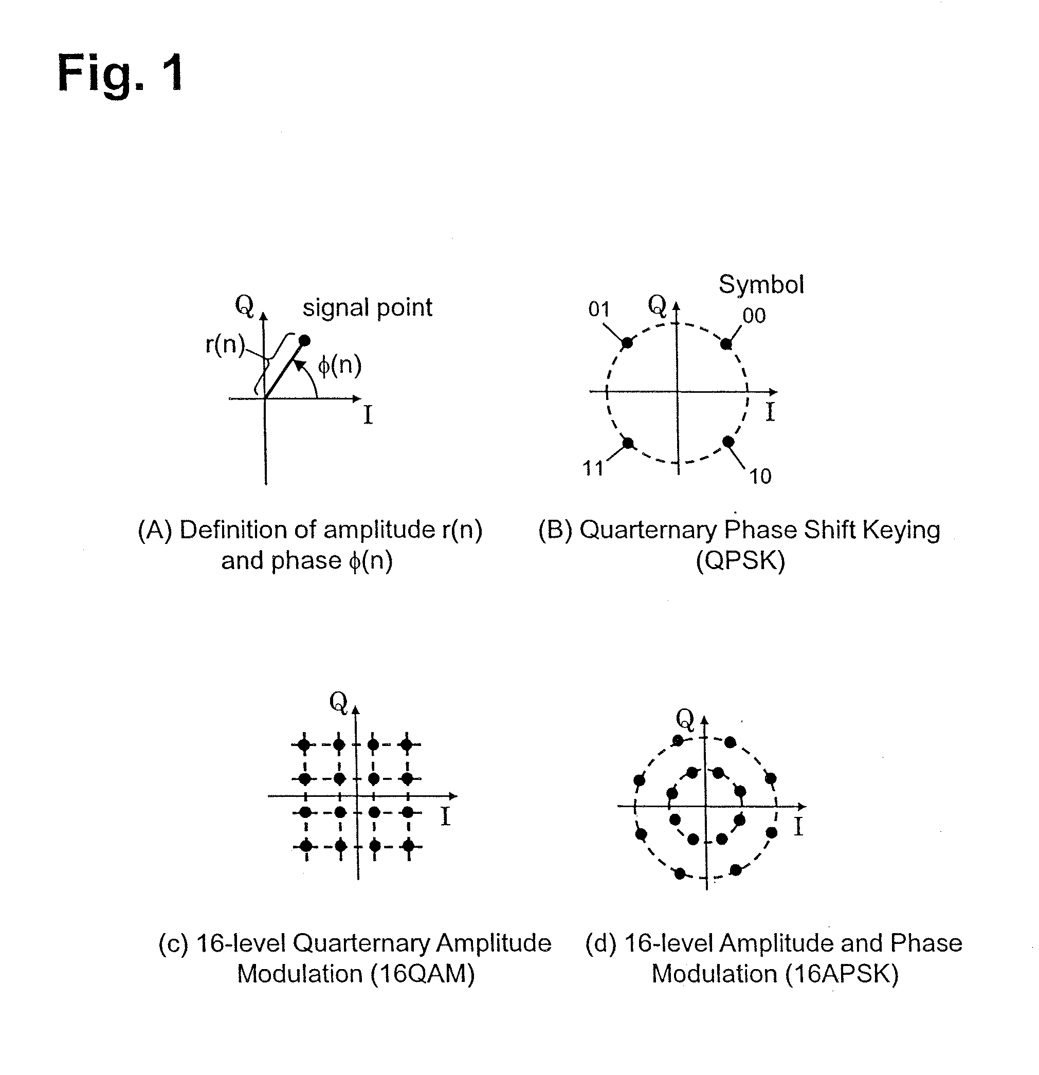
[0077]The features of this configuration reside in that, for example, in addition to the phase modulation in the configuration of FIG. 6, an optical amplitude modulator 211 is introduced so as to modulate even the amplitude of optical signal, and an optical intensity receiver 135 is introduced so as to enable detection of the amplitude component to extend the configuration so that both of the amplitude and the phase can be used for information transmission. As an example of the multilevel amplitude and phase modulation that can be used with the above configuration, there is, for example, 16-level amplitude phase modulation of FIG. 1(D). This modulation can be generated by modulating the amplitude of the optical signal by binary, and modulating the phase by eight l...

third embodiment

[0086]FIG. 11 is a configuration diagram of a direct detection optical multilevel transmission system using the optical multilevel amplitude and phase modulation according to a third embodiment of this embodiment.

[0087]For example, significant features of the third embodiment reside in that coupled modulation of the amplitude and the phase is used, and multistage dependent modulation of the phase is used. Also, a configuration in which the multilevel modulation is generated by the combination of the high-speed binary signal is applied without using the DA converter. The multilevel amplitude and phase modulation available in this configuration is exemplified by an eight-level amplitude phase modulation (or 8-level QAM modulation), for example, in FIG. 12(B). The feature of the 8-level QAM modulation resides in that the modulations of the amplitude and the phase are not completely independent from each other, and a part thereof has a coupled relationship. This modulation signal can be...


PUM


Abstract

In an optical multilevel transmitter (210), a polar representation of an optical multilevel signal (r, φ) is generated by a polar coordinate multilevel signal generation circuit (212), input to an optical amplitude modulator (211) and a polar coordinate type optical phase modulator (201), and output as an optical multilevel modulated signal (213). The polar coordinate type optical phase modulator (201) generates an optical phase rotation proportional to an input voltage, so the modulation distortion of the electric signal is transferred in a linear form to the optical phases of the optical multilevel modulated signal (213). In an optical multilevel receiver (219), a received signal is input to two sets of optical delay detectors (133) and balance receivers (134) and directly demodulated, and a differential phase Δφ for the received signal is calculated by arctangent computation from the output signal. In a phase adaptive equalizer (205), the modulation distortion of the phase is removed by adaptive equalization of the differential phase Δφ. By separately receiving the amplitude components and combining them, the modulation distortion is removed and highly sensitive optical multilevel transmission is achieved.

Description

TECHNICAL FIELD[0001]The present invention relates to an optical transmission system, particularly to an optical transmission system that reduces an optical waveform distortion in an optical information transmission technology, and more particularly to an optical transmitter and receiver, and an optical transmission system, which are suitable for transmission and reception of an optical multilevel information transmitted through an optical fiber.BACKGROUND ART[0002]The amount of information (transmission capacity) transmittable through one optical fiber reaches a limit because a wavelength bandwidth of an optical fiber amplifier has been substantially used up due to an increase in the number of wavelength channels and an increase in a modulation speed of an optical signal. Further, in order to increase the transmission capacity of the optical fiber, there is a need to devise a signal modulation format, crow a large number of optical signals into a limited frequency range, and enhanc...

Claims


Application Information

Patent Timeline
IPC IPC(8): H04B10/18H04B10/556H04B10/67H04B10/69
CPCH04B10/5561H04B10/6971H04B10/677
Inventor KIKUCHI, NOBUHIKO
Owner HITACHI LTD
Why Eureka
Try Eureka