Treatment of a sample with focused acoustic energy

Active Publication Date: 2012-11-08
BIOCARTIS NV
4 Cites 16 Cited by

AI-Extracted Technical Summary

Problems solved by technology

It is a drawback of the known device that its operation is relatively complex requiring different steps for severing the swab and squeezing the acquisition port after the swab has been severed.
This drawback is pa...

Benefits of technology

[0019]In addition, the closed lid may partially close the auxiliary part of the opening, too, in particular when a cutting edge of the lid is extending into the auxiliary part in the closed position of the lid. This further helps having the remainder of the sample carrier being retained in the position corresponding to the auxiliary part of the opening.
[0020]In another preferred embodiment, the lid is designed such that when moving the lid from an open position to a closed position with respect to the opening the sample carrier is forced into the auxiliary part of the opening. This helps reducing steps to be manually executed since simply by moving the lid all three actions may automatically be executed: moving the sample carrier into the auxiliary part of the opening; making an incision in the sample carrier; closing at least part of the opening.
[0021]A further embodiment of a device according to the present disclosure is characterized in that the lid is slidable or rotatable. This embodiment has the advantage that the two types of motion allow easy operation of a lid suitable for forcing a sample carrier and a cutter together.
[0022]A further embodiment of a device according to the present disclosure is characterized in that the device comprises a terminus for indicating the closed position of the lid. This embodiment has the advantage that the terminus provides an easy means for...

Abstract

A device for receiving a sample carrier is provided. The device includes an opening for receiving part of the sample carrier and a cutter for removing a part of the sample carrier. The cutter is coupled to a lid, which is movable to allow the cutter to make an incision in the sample carrier and, at the same time, to close at least part of the opening left open after receipt of the sample carrier. The disclosure further relates to a system comprising such a device and a method for operating such a device.

Application Domain

Technology Topic

Image

  • Treatment of a sample with focused acoustic energy
  • Treatment of a sample with focused acoustic energy
  • Treatment of a sample with focused acoustic energy

Examples

  • Experimental program(1)

Example

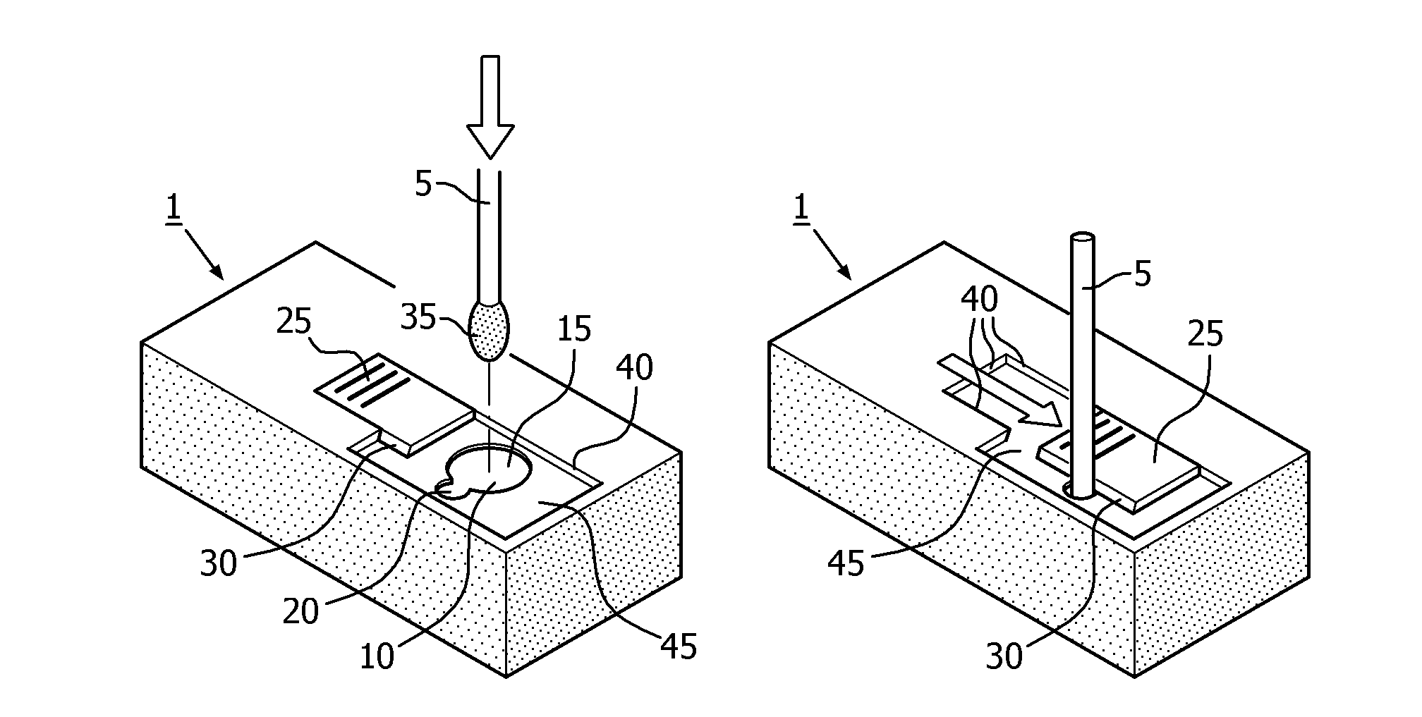
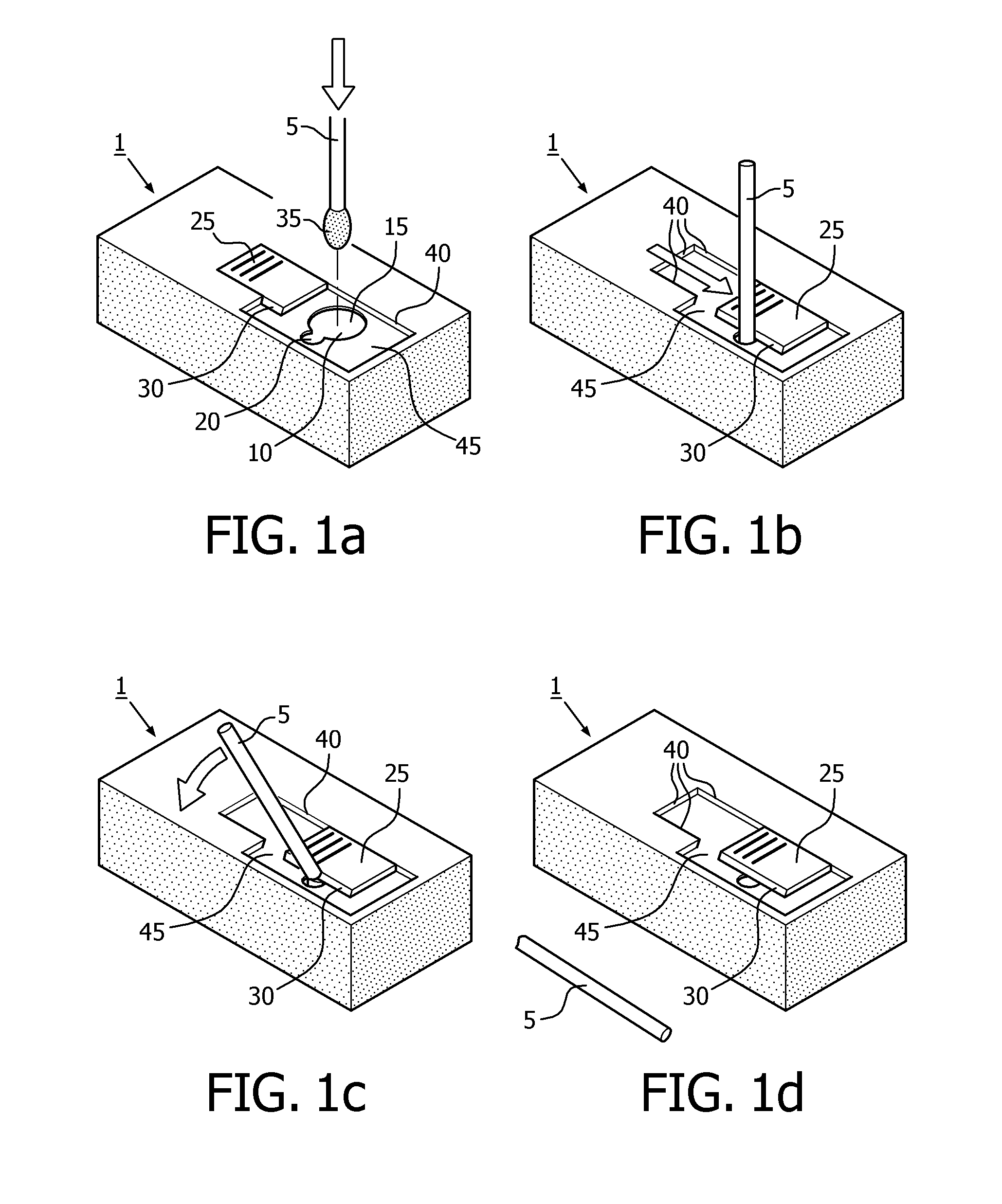
[0038]FIGS. 1a through 1d schematically show an embodiment of a device according to the present disclosure. FIG. 1 shows a device 1 which may be a cartridge insertable into an instrument for handling the cartridge. The cartridge may be a molecular diagnostics cartridge for testing, for instance, a saliva or stool sample. The cartridge is insertable into an instrument suitable for processing a sample in the cartridge in the sense that the instrument may provide, for instance, heating, cooling, cell lysis, and data acquisition services for the sample in the cartridge.
[0039]FIG. 1 further shows a sample carrier 5 which is, in this case, a swab. Alternatively, the sample carrier may be a brush, a stick, etc. Usually, the sample carrier 5 has a rodlike shape. The device 1 comprises an opening 10 for receiving the sample carrier 5. The arrow in FIG. 1a indicates the sample carrier 5 moving towards and partially into the opening 10. In this particular embodiment, the opening 10 comprises a main part 15, through which the sample carrier 5 enters the device 1, and an auxiliary part 20 being adapted for keeping the sample carrier 5 in a specific position. In this case, the dimensions of the auxiliary part 20 are such that the sample carrier 5 closely fits within the auxiliary part 20. Consequently, the sample carrier 5 can be positioned in the auxiliary part 20 after which the sample carrier 5 is kept in its position by the auxiliary part 20 due to the dimensions of one relative to the other. However, for the present disclosure the presence of an auxiliary part 20 is not necessary.
[0040]The device 1 further comprises a lid 25. The lid 25 is slidable as indicated by the arrow in FIG. 1b. In this particular embodiment, the lid 25 comprises a cutting edge 30 which functions as a cutter. When translating the lid 25, the cutting edge 30 makes an incision in a portion of the sample carrier 5 that is extending from the opening 10 and that does not hold sample material. Sample material is present on the tip 35 of the sample carrier 5 (see FIG. 1a). Simultaneously with making the incision, the lid 25 closes at least that part of the opening 10—i.e. in the present embodiment especially the main part 15 of the opening 10—that is left open after insertion of the sample carrier 5 into the opening 10.
[0041]After the incision has been made, the portion of the sample carrier 5 extending from the opening 10 can be broken off and removed. This is shown in FIG. 1c. FIG. 1d shows the device 1 with the lid 25 in the closed position. The lid 25 closes the main part 15 of the opening 10 and part of the auxiliary opening 20. The auxiliary opening 20 per se is closed by the portion of the sample carrier 5 remaining in the device 1 after the part of the sample carrier 5 that originally extended from the opening 10 has been broken off and removed. The piece of the sample carrier 5 that has been broken off and removed is shown next to the device 1.
[0042]FIGS. 1a through 1d further shows a support structure 40. This support structure of 40 guides the lid 25. However, the support structure 40 also limits access to the cutting edge 30 comprised in the lid 25. In the present embodiment, limiting the access to the cutting edge 30 by the support structure 40 is accomplished on the one hand by having the support structure 40 next to the cutting edge 30 when the lid 25 is in the open position (FIG. 1a) and on the other hand by shaping the support structure of 40 in relief. Either of these two measures may be sufficient to limit access to the cutting edge 30. The lid 25 and the opening 10 are located in an area 45 the surface of which is positioned nearer to the interior of the device 1 than the rest of the surface of the device 1 facing the sample carrier 5 in FIG. 1a, i.e. the surface of the cartridge may be recessed in this area 45. In this embodiment, the support structure 40 is basically formed by a brim surrounding the area 45.
[0043]FIG. 2 schematically shows a further embodiment of a device according to the present disclosure. FIG. 2 basically shows the same device as shown in FIG. 1a. Corresponding elements have been given the same reference numerals as in FIGS. 1a through 1d. However, in FIG. 2 there is no auxiliary part 20 of the opening 10. This only serves to illustrate that an auxiliary part 20 is not necessary for the present disclosure in general. Of course, a device according to the present disclosure may be adapted to comprise an auxiliary part 20 as well. The cutting edge 30 comprised in the lid 25 faces in the direction of motion of the lid 25 as indicated by the arrow.
[0044]Again, a sample carrier 5 can be inserted into the opening 10. After the sample carrier 5 has been inserted into the opening 10, the lid 25 is moved towards the opening 10. Once the lid 25 starts to cover the opening 10 the cutting edge 30 starts to make an incision in a part of the sample carrier 5 extending from the opening 10. Once the sample carrier 5 has been sufficiently weakened by the incision, the portion of the sample carrier 5 extending from the opening 10 can be broken off and removed similar to the procedure shown in FIG. 1. However, in the present embodiment, the lid 25 is able to completely cover the opening 10. This is a result of the cutter, in this case the cutting edge 30, being arranged in the direction of motion of the lid 25. In the present embodiment, the cutting edge 30 is inclined at an angle different from 90° relative to the direction of motion of the lid 25. This enhances the cutting function. As with all embodiments of the present disclosure, the cutting edge 30 or, more generally, the cutter may be serrated (not shown).
[0045]FIG. 3a through 3c schematically show further embodiments of devices according to the present disclosure. FIGS. 3a through 3c show devices similar to those shown in FIGS. 1 and 2. Similar elements have been given identical reference numerals. However, in FIGS. 3a through 3c, a rotational motion is used to make an incision in a sample carrier rather than a translational motion as in FIGS. 1 and 2.
[0046]In FIG. 3a, the device 1 comprises a rotatable lid 50. The rotatable lid 50 comprises a grip 55 allowing the lid 50 to be rotated around the axis indicated by the dashed line. The device 1 comprises an opening 10 for receiving a sample carrier 5. The opening 10 comprises a main part 15 and an auxiliary part 20 just as in FIG. 1. However, as already shown in FIG. 2 this is not mandatory.
[0047]The auxiliary part 20 is orientated towards the axis of rotation of the lid 50, i.e. it is arranged closer to the center of the lid 50 than the main part 15. The lid 50 further comprises a disk 60. The disk 60 comprises different areas having different radii. The first area with radius R1 leaves the opening 10 open to receive sample carrier 5. The second area has a radius R2 which is larger than R1. The second area with radius R2 forms a cutter in that the second area comprises a cutting edge 30. Radius R2 is such that the cutting edge 30 makes an incision into the sample carrier 5 when the second area moves along the sample carrier 5. After the incision has been made, the part of the sample carrier 5 that extends from the device 1 can be broken off and removed just as in FIGS. 1 and 2. After that, the lid 50 can be rotated further such that the third area with radius R3, R3 being larger than R2, completely covers the opening 10.
[0048]FIG. 3b shows a device 1 similar to that shown in FIG. 3a. Again, similar elements have been given identical reference numerals. However, this time the auxiliary part 20 of the opening 10 is circumferentially arranged next to the main part 15 such that when the lid 50 rotates it hits the main part 15 and the auxiliary part 20 subsequently. The lid 50 comprises a first area with radius R1 such that this first area leaves the opening 10 open for receiving a sample carrier 5. The lid 50 further comprises a cutting area 65 comprising a cutting edge 30 similar to the cutting edge 30 shown in FIG. 2. As the lid 50 rotates in the direction indicated, the cutting edge 30 engages the sample carrier 5. Again, an incision is made in the sample carrier 5 after which the part of the sample carrier 5 extending from the device 1 can be broken off and removed. After that, the lid 50 can be rotated further such that a second area with radius R2, R2 being larger than R1, completely covers the opening 10.
[0049]FIG. 3c shows a device 1 similar to the devices shown in FIGS. 3a and 3b. Again, similar elements have been given identical reference numerals. In the present embodiment, the auxiliary opening 20 is orientated away from the axis of rotation of the lid 50, i.e. it is arranged farther from the center of the lid 50 than the main part 15. This arrangement has the advantage that the lid 50 tends to push the sample carrier 5 into the auxiliary part 20 of the opening 10 when the lid 50 forces the cutting edge 30 and the sample carrier5 together. The lid 50 comprises a first area with a radius R1 such that it leaves the opening 10 open for receiving a sample carrier 5. The lid 50 further comprises a second area with radius R2, R2 being larger than R1. The second area comprises the cutting edge 30. R2 is such that the cutting edge 30 is able to make an incision in the sample carrier 5 when the cutting edge 30 passes along and partially over the auxiliary part 20 in which the sample carrier 5 is kept in a fixed position. Again, after the incision has been made the part of the sample carrier 5 extending from the device 1 can be broken off and removed. If the lid 50 is rotated over a sufficient angle, the second area of the lid 50 is able to completely cover the main part 15 of the opening 10. The auxiliary part 20 of the opening 10 is closed by the part of the sample carrier 5 that remains with a device 1 after the rest of the sample carrier 5 has been broken off and removed. Alternatively, the lid 50 may further comprise a third area with radius R3 (not shown), R3 being larger than R2 (see for instance FIG. 3a for an analogous situation). If R3 is large enough the lid 50 may be rotated such that the third area with radius R3 covers both the main part 15 and the auxiliary part 20 of the opening 10 after an incision has been made in the sample carrier 5.
[0050]FIGS. 4a through 4c schematically show further embodiments of a device according to the present disclosure.
[0051]FIG. 4a shows a device similar to the device 1 shown in FIG. 1. Again, similar elements have been given identical reference numerals. However, the device 1 in the present figure comprises a number of features not shown in FIG. 1. It will be obvious to a person skilled in the art any of that these features of the present figure may be combined with the device shown in the other figures.
[0052]In FIG. 4a the cutting edge is comprised in the brim of the auxiliary part 20 of the opening 10 instead of in the lid 25. This allows greater freedom in choosing the thickness of the lid 25 which may be beneficial when employing manufacturing methods such as cast molding. If, for instance, a lid comprising a cutting edge becomes too thin, it might bend when forcing a sample carrier and a cutting edge together due to the surface of the cutting edge being inclined at a non-90° angle relative to the direction of motion of the lid while the sample carrier is at 90° relative to this direction.
[0053]FIG. 4a further shows a lid 25 that has an additional appendage 25a as compared to the lid 25 shown in FIG. 1. With the additional appendage 25a the lid 25 is able to cover both the main part 15 and the auxiliary part 20 of the opening 10 if the lid 25 is moved far enough from the open position towards the closed position.
[0054]The lid 25 shown in the present figure further comprises an area 25b the brim of which is inclined at a non-90° angle relative to the direction of motion of the lid 25. Consequently, when moving the lid 25 to the closed position, the narrower end of the area 25b passes by the sample carrier 5 in the auxiliary part 20 of the opening 10 until the inclined brim of the area 25b contacts the sample carrier 5. From that point on, the inclined brim of the area 25b pushes the sample carrier 5 into the auxiliary part 20 of the opening 10.
[0055]If the dimensions of the auxiliary part 20 are such that they allow the sample carrier 5 to move further into the auxiliary part 20, pushing with the inclined brim of the area 25b will lead to the sample carrier 5 moving along the cutting edge 30 comprised in the brim of the auxiliary part 20. Motion of the sample carrier 5 along the cutting edge 30 further enhances the making of an incision by the cutting edge 30 into the sample carrier 5. This can be achieved with, for instance, an auxiliary part 20 that extends like a slit (not shown) from the main part 15 of the opening 10. The width of the auxiliary part 20 and the width of a sample carrier 5 are then such that they together allow the sample carrier 5 to be fixed in a specific orientation in the auxiliary part 20, while the slit forming the auxiliary part 20 is long enough to allow the sample carrier 5 to move further from the main part 15 into the slit under the pushing force exerted using the inclined brim of the area 25b. In short, the inclined brim of the area 25b is used to push the sample carrier 5 further into the auxiliary part 20 resulting in the sample carrier 5 moving along the cutting edge 30 comprised in the brim of the auxiliary part 20.
[0056]The auxiliary part 20 of the opening 10 may be shaped to further facilitate keeping a sample carrier in a fixed position once the sample carrier is inserted into the auxiliary part. To this end, the auxiliary part may become narrower (not shown) going from the position at which the auxiliary part 20 is coupled to the main part 15 to the closed end of the auxiliary part.
[0057]The shape of the area 45a is complimentary to part of the shape of the lid 25. Consequently, the brim of the area 45a forms a terminus for the movement of the lid 25 from the open to the closed position. If the lid 25 is moved against the brim of the area 45a an operator of the device 1 can be sure that the opening 10 is fully closed. Ensuring that the opening 10 is closed is especially relevant if the device 1 or the sample carried by the sample carrier 5 comprise hazardous materials such as chemical or biological substances. A color coding may be applied to the lid 25, the area 45a, and/or the area 47 to indicate that the lid 25 has reached the closed position. The lid 25 and the area 47 may, for instance, be given a color (that may be the same for the lid 25 and the area 47) that is different from the color of the area of 45a. As long as the color of the area 45a is still visible, the lid 25 has not yet reached the closed position. It will be clear to the skilled person that the terminus may be provided in different forms. As an alternative to the embodiment shown in the present figure, the area 45a might comprise a protrusion which the lid 25 touches in the closed position. The lid 25 might also comprise an indentation the shape of which is complimentary to the shape of the protrusion.
[0058]FIG. 4b schematically shows an embodiment of the cutting edge 30 for the device 1 shown in FIG. 4a as viewed along the line IVbc-IVbc in FIG. 4a. The cutting edge lies below a top plane 90 defining the auxiliary part 20 of the opening 10 relative to the direction of receipt of the sample carrier.
[0059]FIG. 4c schematically shows a preferred embodiment of the cutting edge 30 for the device 1 shown in FIG. 4a as viewed along the line IVbc-IVbc in FIG. 4a. The cutting edge 30 now lies in the top plane 90 defining the auxiliary part 20 of the opening 10. This embodiment has the advantage that the position at which the sample carrier 5 can be broken off after an incision has been made by the cutting edge 30 is better defined than with the cutting edge 30 shown in FIG. 4b. In the present embodiment, the sample carrier 5 will break at the position of the cutting edge 30 if the sample carrier 5 is sufficiently bent after an incision has been made by the cutting edge 30. In FIG. 4b the sample carrier 5 might break somewhere above the cutting edge 30 because in that arrangement the sample carrier 5 has more room to bend as indicated by the dashed lines in that figure.
[0060]FIG. 4c further shows a support 100 for limiting the motion of the sample carrier 5 during the making of an incision in the sample carrier 5 or during bending of the sample carrier 5 in order to break it after an incision has been made. This support 100 may or may not extend along the whole length of the part of the sample carrier 5 that has been inserted into a device according to an embodiment of the present disclosure. In the present figure, the support 100 limits bending of the inserted part of the sample carrier 5 when the part of the sample carrier 5 that extends from the device is bended towards the left of the figure. To limit bending in another direction, the support 100 should be positioned in a correspondingly different location from the one shown in the present figure as will be clear to a person skilled in the art. If the part of the sample carrier 5 that extends from the device is bent towards the right of the figure, the support 100 should be positioned left of the opening of the auxiliary part 20 instead of to the right as shown in FIG. 4c. The support 100 may extend from the brim of the auxiliary part 20 into a device according to an embodiment of the present disclosure. As an alternative or in addition to the support 100 shown in the present figure, motion of the sample carrier 5 may be limited by a wall portion comprised in the wall defining the volume into which a sample carrier 5 is inserted. In that case, the support 100 shown in the present figure may be comprised in a wall bounding the volume 200 into which the sample carrier 5 has been inserted. Alternatively or in addition, motion of a sample carrier 5 may be limited both by a dedicated support 100 and a wall portion comprised in the wall defining the volume into which the sample carrier 5 is inserted. In that case, the support 100 may limit motion in one direction whereas the wall portion limits motion in another direction.
[0061]FIG. 5 schematically shows an embodiment of a system according to the present disclosure. The present figure shows a device 1 similar to the devices shown in any of the previous figures. In this particular embodiment, the device 1 is identical to the device 1 shown in FIG. 1d. Also shown is an instrument 70 for receiving and handling the device 1. The system 75 comprises the instrument 70 and the device 1. In this embodiment, the device 1 forms a cartridge that can be inserted into the instrument 70 after part of a sample carrier that has been used to provide the device 1 with sample material has been broken off and removed following the procedure outlined in the previous figures. The device 1 may hold the ingredients for performing a chemical reaction, whereas the instrument 70 provides facilities for performing and detecting the chemical reaction. The instrument 70 may provide, for instance, heating, cooling, cell lysis, and data acquisition facilities to the device 1. The device 1 may be a cartridge for detecting the presence of one or more pathogens in a sample, for instance a saliva, stool, or blood sample inserted into the device 1 using a sample carrier as shown in the previous figures. Different cartridges, that are different devices 1, may be inserted into the instrument 70 for performing different tests.
[0062]FIG. 6 schematically shows an embodiment of a method according to the present disclosure. In step 80 a sample carrier is placed in an opening comprised in a device for receiving the sample carrier. Next, in step 85, a lid is moved from a position in which the opening is open to a position in which the opening is closed. During this motion, the lid engages the sample carrier with a cutter which makes an incision in the sample carrier. Once the incision has been made, the part of the sample carrier at that extends from the device through the opening can be broken off and removed.
[0063]It should be noted that the above-mentioned embodiments illustrate rather than limit the present disclosure, and that those skilled in the art will be able to design many alternative embodiments without departing from the scope of the appended claims. In the claims, any reference signs placed between parentheses shall not be construed as limiting the claim. The word “comprising” does not exclude the presence of elements or steps other than those listed in a claim. The word “a” or “an” preceding an element does not exclude the presence of a plurality of such elements. In the system claims enumerating several means, several of these means can be embodied by one and the same item of computer readable software or hardware. The mere fact that certain measures are recited in mutually different dependent claims does not indicate that a combination of these measures cannot be used to advantage.

PUM

PropertyMeasurementUnit
Length
Width
Dimension
tensileMPa
Particle sizePa
strength10

Description & Claims & Application Information

We can also present the details of the Description, Claims and Application information to help users get a comprehensive understanding of the technical details of the patent, such as background art, summary of invention, brief description of drawings, description of embodiments, and other original content. On the other hand, users can also determine the specific scope of protection of the technology through the list of claims; as well as understand the changes in the life cycle of the technology with the presentation of the patent timeline. Login to view more.

Similar technology patents

Cerium sulfate chelated sulfur dioxide, a preparation method and a use thereof

ActiveUS20190185336A1Step be reduceAvoid appearanceRare earth metal sulfatesChemical analysis using titrationSolventSulfur dioxide
Owner:SOUTH CHINA NORMAL UNIVERSITY

Classification and recommendation of technical efficacy words

  • Step be reduce
  • Easy to operate

Intelligent computer cabling

InactiveUS20060081716A1Step be reduceEliminates complexityProgram controlRecord carriers used with machinesEmbedded systemTransfer system
Owner:DATA DRIVE THRU

Dual-chamber syringe and associated connecting systems

InactiveUS20160175537A1Step be reduceImprove techniqueInfusion syringesCheck valvesQuality assuranceSyringe
Owner:THORNE CONSULTING FOR INT PROPERTY LLC
Why Eureka
Try Eureka