

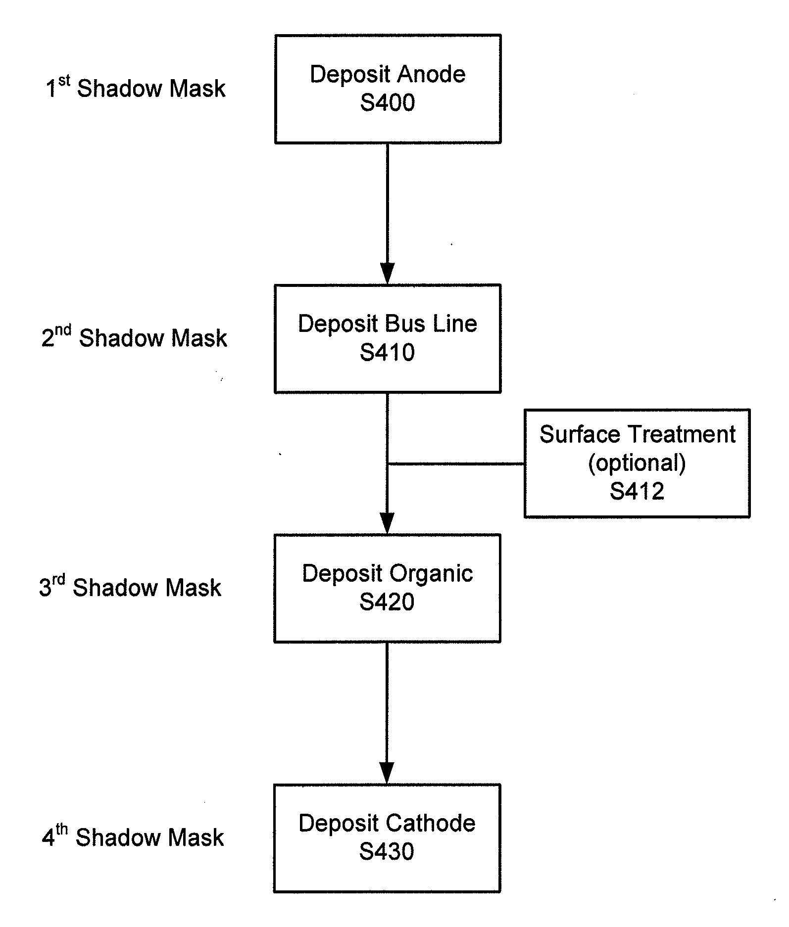
Process For Fabricating OLED Lighting Panels
a technology of oled lighting panels and manufacturing processes, which is applied in the manufacture of electrode systems, electric discharge tubes/lamps, and discharge tubes luminescent screens, etc., can solve the problems of reducing device efficacy, difficult to dispose uniform thin films over bus lines, and non-uniform luminance, so as to improve the luminance uniformity of large-area oled light panels, reduce the probability of electrical shorting, and enhance the emissive area and shelf life of devices
- Summary
- Abstract
- Description
- Claims
- Application Information
AI Technical Summary
Benefits of technology
Problems solved by technology
Method used
Image

Examples
Embodiment Construction
[0098]It is understood that the invention is not limited to the particular methodology, protocols, and reagents, etc., described herein, as these may vary as the skilled artisan will recognize. It is also to be understood that the terminology used herein is used for the purpose of describing particular embodiments only, and is not intended to limit the scope of the invention. It also is be noted that as used herein and in the appended claims, the singular forms “a,”“an,” and “the” include the plural reference unless the context clearly dictates otherwise. Thus, for example, a reference to “a bus line” is a reference to one or more bus lines and equivalents thereof known to those skilled in the art.
[0099]Unless defined otherwise, all technical and scientific terms used herein have the same meanings as commonly understood by one of ordinary skill in the art to which the invention pertains. The embodiments of the invention and the various features and advantageous details thereof are e...
PUM
| Property | Measurement | Unit |
|---|---|---|
| area | aaaaa | aaaaa |
| brightness | aaaaa | aaaaa |
| luminance | aaaaa | aaaaa |
Abstract
Description
Claims
Application Information