Photoluminescence color display

a color display and photoluminescence technology, applied in non-linear optics, instruments, optics, etc., can solve the problems of wasting significant amount of backlight intensity, complicated driving circuitry, and unfavorable photoluminescence, and achieves better contrast ratio, purity and realism, and 90% efficiency of light output

Active Publication Date: 2012-11-15
INTEMATIX
View PDF13 Cites 170 Cited by
  • Summary
  • Abstract
  • Description
  • Claims
  • Application Information

AI Technical Summary

Benefits of technology

[0042]The current LCD technology that employs color filters has only about a 10 to 20 percent efficiency of light output that is achievable at the front of a liquid crystal display. By contrast, the present embodiments using a photoluminescence material (phosphor and / or quantum dots) based color rendering scheme, including using red-green phosphor and / or quantum dots elements plus blue LED illumination, can have up to 90 percent efficiency of light output. With a broader color range, phosphors and / or quantum dots and LED backlight together render truer skin tones and vivid reds and greens, offering better contrast ratios, purity and realism, and meeting new consumer expectations.

Problems solved by technology

This approach unfortunately requires complex driving circuitry to properly control the intensities of the three different color LEDs since different circuitry is necessary because each of the LEDs demands different drive conditions.
Unfortunately the white light product of such LEDs does not match well with the color filters used in current LCDs, and a significant amount of the backlight intensity is wasted.

Method used


Image

  • Photoluminescence color display
  • Photoluminescence color display
  • Photoluminescence color display

Examples


Embodiment Construction

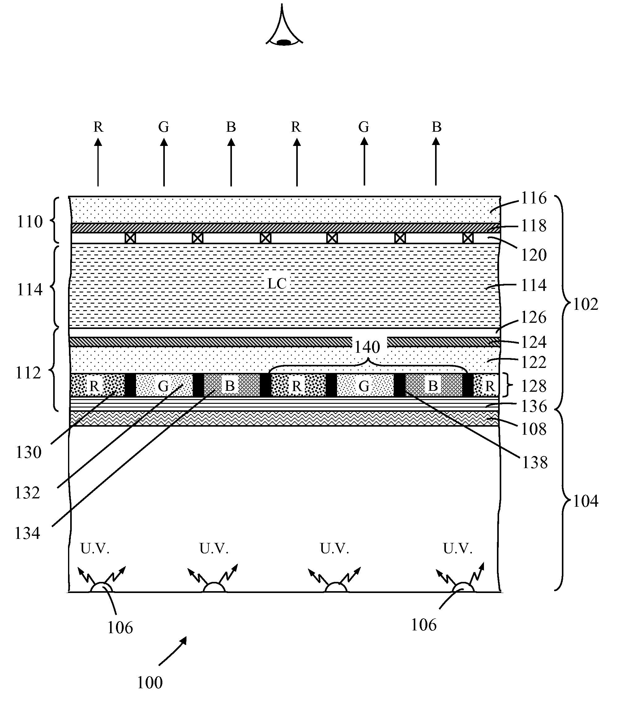
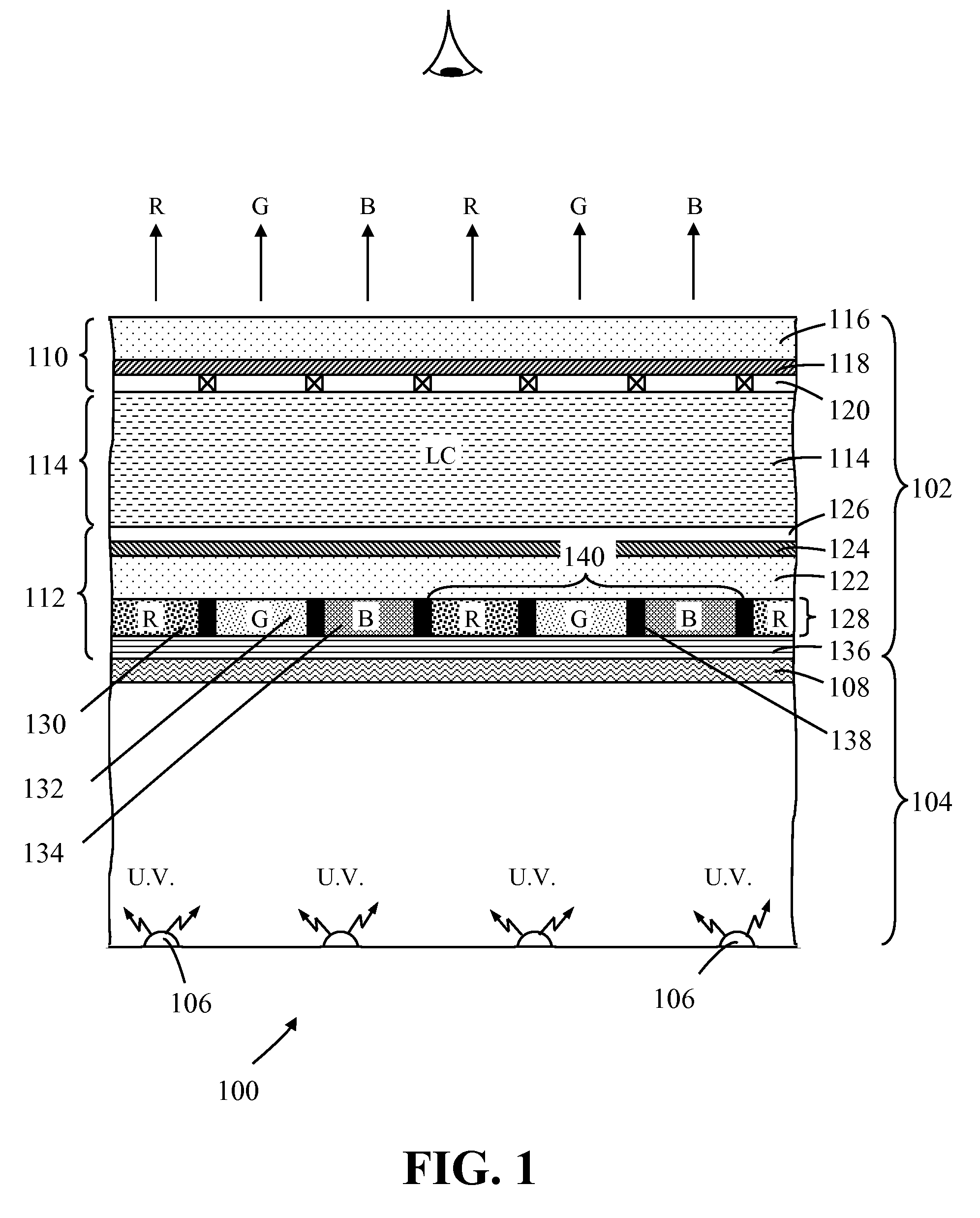
[0056]Disclosed herein is a novel color rendering scheme designed to improve and enhance the brightness and sharpness of an electronic display, such as a liquid crystal display (LCD).

[0057]Embodiments of the present invention incorporate two key components: 1) a photoluminescence color panel (photoluminescence color-elements plate) having regions of photoluminescence material corresponding to each of the different color pixel areas of the display, and 2) a monochromatic or quasi-monochromatic short-wavelength excitation light source for exciting the photoluminescence material on the color panel. Additionally, a wavelength selective filter can be provided between the photoluminescence color panel and the excitation light source in order to prevent cross contamination of light among the different pixel areas of the display.

[0058]Referring to FIG. 1 there is shown a schematic cross-sectional representation of a photoluminescence color LCD 100 according to a first embodiment of the inve...


PUM

PropertyMeasurementUnit
wavelengthaaaaaaaaaa

Abstract

A photoluminescence color display comprises a display panel that displays red, green and blue pixel areas, an excitation source operable to generate excitation radiation for operating the display, and a photoluminescence color-element plate. The color-element plate comprises at least one photoluminescence material, such as a phosphor material or quantum dots, that is operable to emit light corresponding to red, green and blue pixel areas of the display in response to said excitation radiation. Additionally, the photo-luminescence color display comprises a wavelength selective filter that is provided between the color-element plate and the excitation source. The filter has a transmission characteristic that allows the passage of excitation radiation from the excitation source to excite the at least one photoluminescence material whilst preventing the passage of photoluminescence light back to the excitation source thereby prevent cross contamination of light among the different pixel areas of the display.

Description

CLAIM OF PRIORITY[0001]The present application is a continuation-in-part of U.S. patent application Ser. No. 11 / 824,979 filed Jul. 3, 2007, entitled “PHOTO-LUMINESCENCE COLOR LIQUID CRYSTAL DISPLAY”, which claims the benefit of priority to U.S. Provisional Application No. 60 / 819,420 filed Jul. 6, 2006, the specification and drawings of which applications are incorporated herein by reference in their entirety.BACKGROUND OF THE INVENTION[0002]1. Field of the Invention[0003]The present invention relates to the field of color displays, such as flat panel displays and color liquid crystal displays (LCDs), which convert electrical signals into color images. In particular, the invention concerns color, transmissive displays in which photoluminescence materials are used to generate color light in response to excitation radiation from a backlight, such displays being termed photoluminescence color displays or photoluminescent color displays.[0004]2. Description of the Related Art[0005]The li...

Claims


Application Information

Patent Timeline
Patent Type & Authority Applications(United States)
IPC IPC(8): G02F1/1335
CPCG02F1/133617G02F2203/34G02F2001/133614G02F2001/133567G02F1/133509G02F1/133514G02F2203/02G02F2203/055G02F1/133567G02F1/1333G02F1/1335G02F1/133614
Inventor LI, YI-QUNDONG, YISHAN, WEI
Owner INTEMATIX
Why Eureka
Try Eureka