Method of controlling fuel cell system

a fuel cell and system control technology, applied in battery/fuel cell control arrangement, electrochemical generators, transportation and packaging, etc., can solve the problems of electric power loss, undesirable lowering of etc., and achieve the effect of lowering output efficiency of fuel cell system

Inactive Publication Date: 2012-11-15
HONDA MOTOR CO LTD
View PDF4 Cites 8 Cited by
  • Summary
  • Abstract
  • Description
  • Claims
  • Application Information

AI Technical Summary

Benefits of technology

[0006]As described above, in JP2011-015580A, after the excessive electric power in the power generation suspension mode is stored in the battery, the stored electric power is used for acceleration of the vehicle. Thus, if the frequency of charging / discharging of the battery is increased, electric power loss occurs due to such charging / discharging, and the output efficiency in the fuel cell system may be lowered undesirably.

Problems solved by technology

Thus, if the frequency of charging / discharging of the battery is increased, electric power loss occurs due to such charging / discharging, and the output efficiency in the fuel cell system may be lowered undesirably.

Method used


Image

  • Method of controlling fuel cell system
  • Method of controlling fuel cell system
  • Method of controlling fuel cell system

Examples


first embodiment

A. First Embodiment

1. Description Regarding Overall Structure

[1-1. Overall Structure]

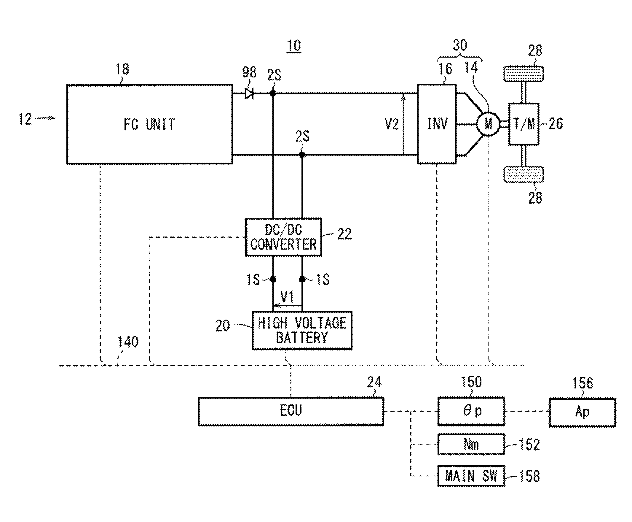
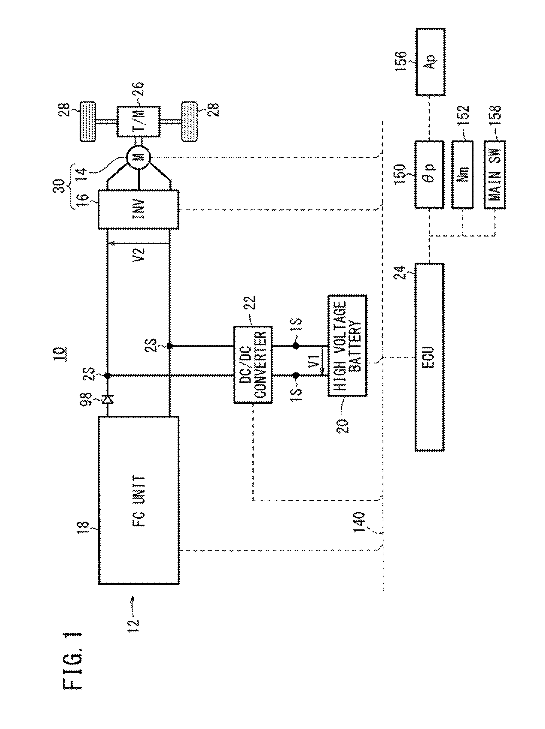
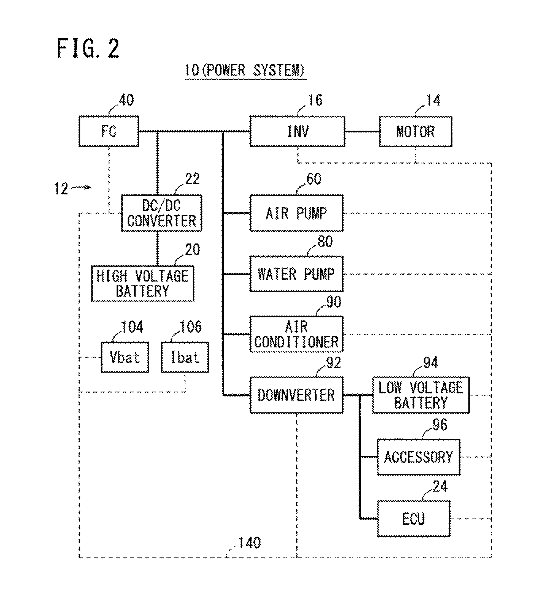
[0048]FIG. 1 is a diagram schematically showing the overall structure of a fuel cell vehicle 10 (hereinafter referred to as the “FC vehicle 10”) equipped with a fuel cell system 12 (hereinafter referred to as the “FC system 12”) according to a first embodiment of the present invention. FIG. 2 is a block diagram showing a power system of the FC vehicle 10. As shown in FIGS. 1 and 2, the FC vehicle 10 includes a traction motor 14 and an inverter (auxiliary device) 16 in addition to the FC system 12.

[0049]The FC system 12 includes a fuel cell unit 18 (hereinafter referred to as the “FC unit 18”), a high voltage battery (hereinafter referred to as the “battery 20”) (energy storage device), a DC / DC converter 22, and an electronic control unit (control device) 24 (hereinafter referred to as the “ECU 24”).

[1-2. Drive System]

[0050]The motor 14 generates a driving force based on the electric power supplied f...

second embodiment

B. Second Embodiment

[0164]In the second embodiment, basically, hardware structure identical to that of the first embodiment is adopted. Hereinafter, like reference numerals designate like elements. In the second embodiment, the ECU 24 uses a method of energy management of the FC system 12 which is different from the method of the first embodiment.

1. Energy Management of FC System 12

[0165]FIG. 23 is a flow chart where the ECU 24 performs energy management (S3 of FIG. 5) of the FC system 12. As in the case of step S21 of FIG. 12, in step S81, the ECU 24 determines whether or not the idling power generation suppression mode should be selected. Specifically, as a condition of the idling power generation suppression mode, the ECU 24 determines whether or not the vehicle velocity V is equal to or less than the threshold value THV1 and the system load Psys is equal to or less than the threshold value THPsys1. If the vehicle velocity V is more than the threshold value THV1 or the system loa...


PUM

PropertyMeasurementUnit
electric potential v1aaaaaaaaaa
electric potential v2aaaaaaaaaa
electric potential v3aaaaaaaaaa

Abstract

In an FC system of an FC vehicle, if a control device determines that conditions of an idling power generation suppression mode of a FC are satisfied, the control device sets the voltage of the FC to a predetermined voltage value outside a voltage range where an oxidation-reduction of platinum proceeds, and controls a reactant gas supply apparatus to change a supply amount of air such that the FC has an output in accordance with the electric power required by a load.

Description

CROSS-REFERENCE TO RELATED APPLICATION[0001]This application is based upon and claims the benefit of priority from Japanese Patent Applications No. 2011-107144 filed on May 12, 2011 and No. 2011-197777 filed on Sep. 12, 2011, of which the contents are incorporated herein by reference.BACKGROUND OF THE INVENTION[0002]1. Field of the Invention[0003]The present invention relates to a method of controlling a fuel cell system including a fuel cell, an energy storage device capable of storing electric power supplied from the fuel cell, and a load to which electric power is supplied from at least one of the fuel cell and the energy storage device.[0004]2. Description of the Related Art[0005]In a conventional technique, a fuel cell system for suppressing degradation of a fuel cell used in a fuel cell vehicle or the like is proposed, and in the fuel cell system, power generation is performed in a manner that the oxidation reduction electrical potential is avoided (Japanese Laid Open Patent P...

Claims


Application Information

Patent Timeline
Patent Type & Authority Applications(United States)
IPC IPC(8): H01M8/04
CPCH01M8/04619H01M8/04753H01M8/0488Y02T90/34B60L11/1887B60L2210/14Y02T10/7225Y02E60/50B60L58/40Y02T10/70Y02T10/72Y02T90/40
Inventor KAZUNO, SHUICHISAEKI, HIBIKIIGARASHI, DAISHI
Owner HONDA MOTOR CO LTD
Why Eureka
Try Eureka