Charged-particle beam lithographic apparatus and method of manufacturing device

a lithographic apparatus and charge technology, applied in photomechanical apparatus, instruments, nuclear engineering, etc., can solve the problems of prolonging the time required to reduce the pressure in the chamber after the end of cleaning, unable to satisfactorily clean the interior of the aperture, and unable to meet the cleaning needs of the aperture, so as to reduce the pressure in the chamber effect of rising

Inactive Publication Date: 2012-11-15
CANON KK
View PDF12 Cites 25 Cited by
  • Summary
  • Abstract
  • Description
  • Claims
  • Application Information

AI Technical Summary

Benefits of technology

[0006]The present invention provides, for example, a technique advantageous in reduction of a rise in pressure in the chamber upon cleaning of apertures.

Problems solved by technology

In the charged-particle beam lithographic apparatus, when an aperture plate having apertures is present in the path through which an active species (radicals fall into the concept of the active species) flows, the conductance of the portion where the aperture plate is placed is low so the active species is inactivated, thus making it impossible to satisfactorily clean the interior of the apertures.
Then, the time required to reduce the pressure in the chamber after the end of cleaning prolongs, so the downtime may prolong.

Method used


Image

  • Charged-particle beam lithographic apparatus and method of manufacturing device
  • Charged-particle beam lithographic apparatus and method of manufacturing device
  • Charged-particle beam lithographic apparatus and method of manufacturing device

Examples


example 1

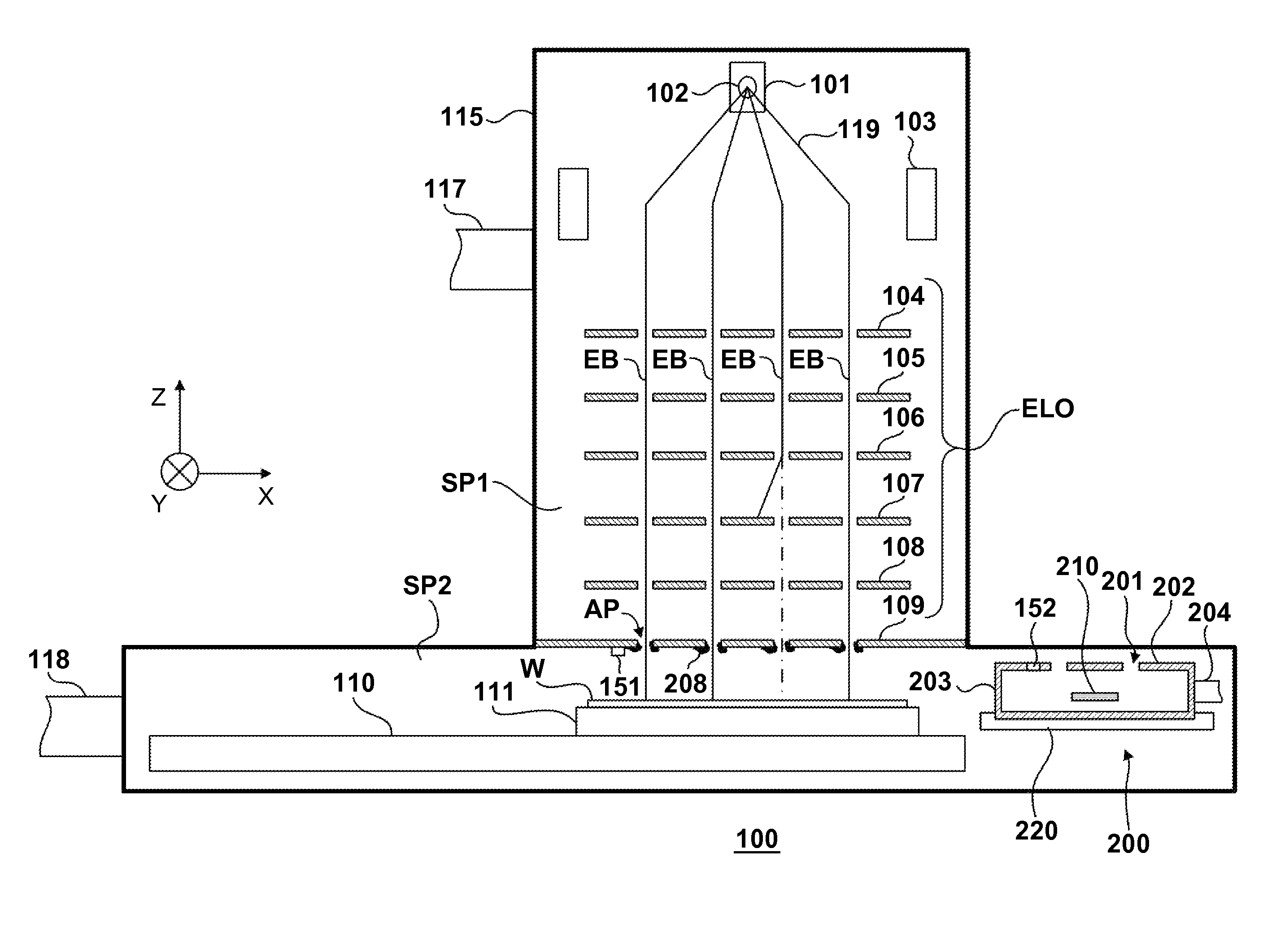
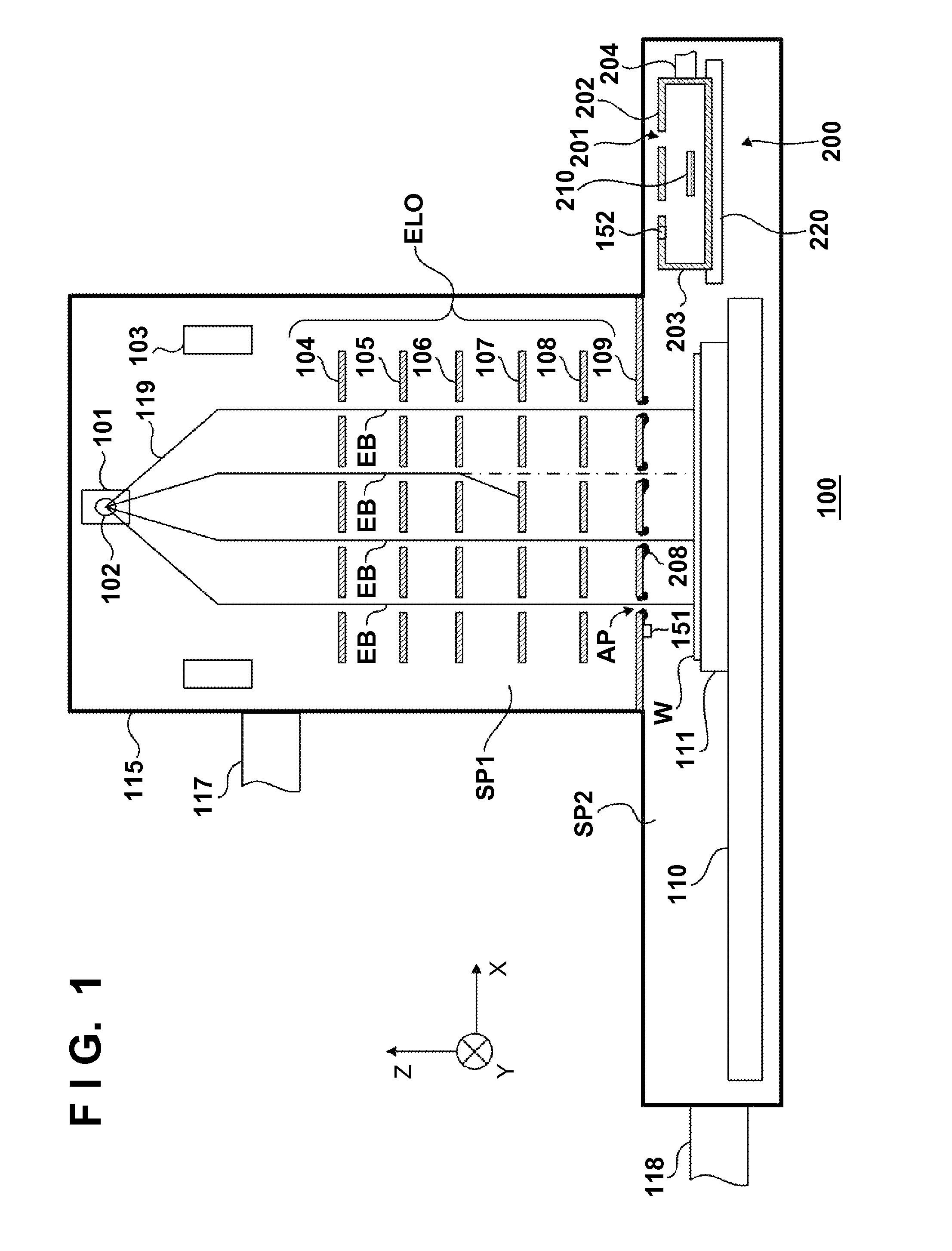
[0038]Hydrogen gas is supplied from a supply portion 204 into a case 203 at a flow rate Q=1.35 Pa·m3 / sec so that hydrogen radicals are generated by an active species source 210 and emitted through emitting holes 201. The hydrogen radicals pass through apertures in an electrostatic lens array 109 (electrode plates 301, 302, and 303). At this time, some of the hydrogen radicals react with deposits 208 to generate a volatile gas. The volatile gas and hydrogen gas are exhausted from a chamber 115 via an exhaust port 117. Note that when the exhaust of those gases from the exhaust port 117 was regulated so that the exhaust rate is 0.1 m3 / sec on the side of the electrode plate 301, the amount of hydrogen gas exhausted from the exhaust port 117 became equal to that of hydrogen gas (containing hydrogen radicals) emitted from the emitting holes 201 of the case 203. The diameter of each emitting hole 201 is 60 μm, and the thickness of an emitting hole plate 202 is 300 μm. The diameter of each ...

example 2

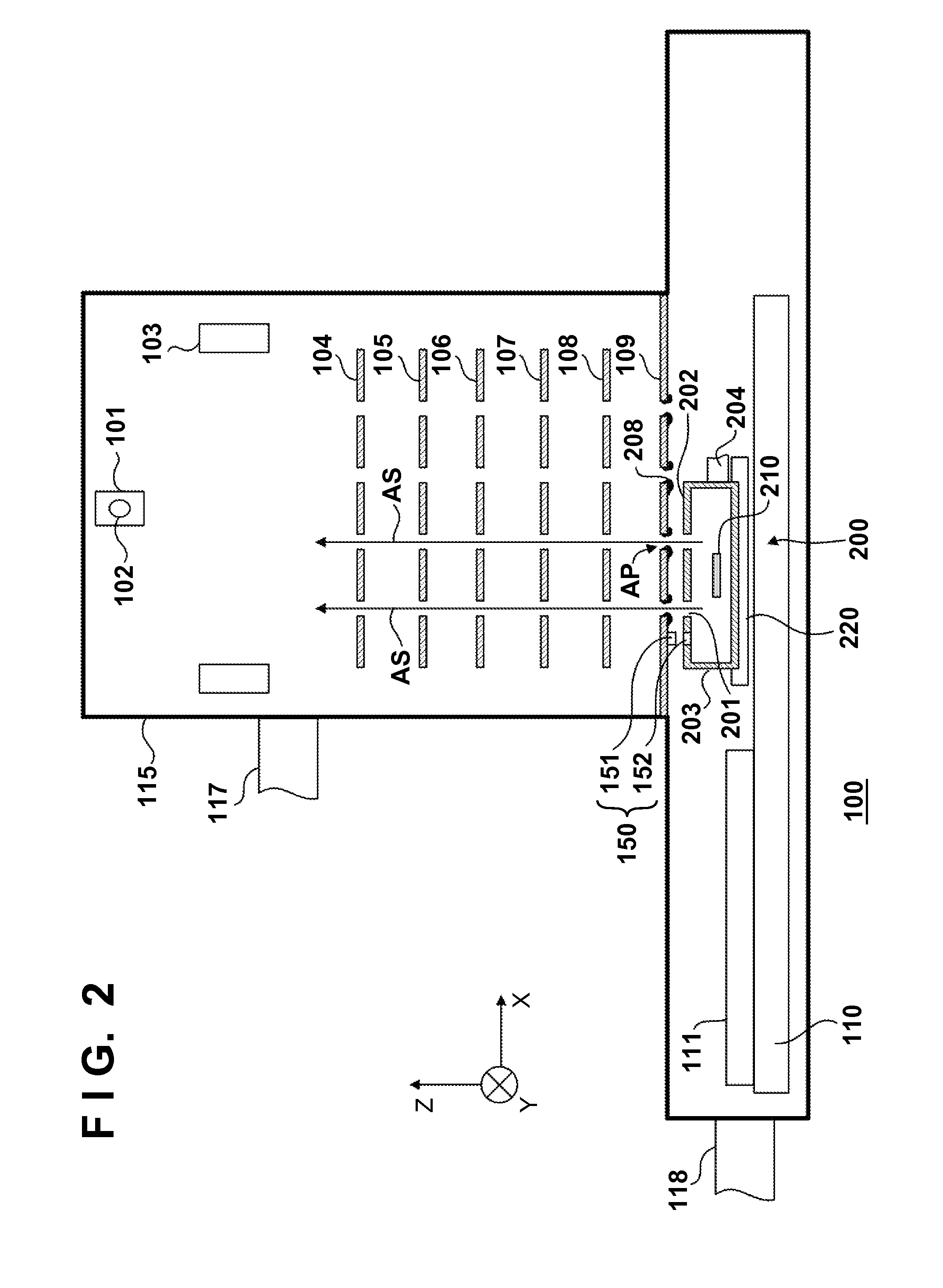
[0043]In Example 2, the electrostatic lens array 109 schematically shown in FIG. 7A is cleaned using a cleaning unit including a case 203 having an emitting hole plate 202 schematically shown in FIG. 7B.

[0044]First, an origin position is determined in the same way as in Example 1. The case 203 is positioned so that emitting holes 201 in the case 203 and a group of apertures AP to be cleaned in the electrostatic lens array 109 are aligned with each other in the Or direction (X and Y directions), based on the array information of the emitting holes 201. Upon this operation, the group of apertures AP to be cleaned is cleaned by an active species AS emitted from the emitting holes 201. The case 203 is driven by a driving mechanism 220 in the first embodiment, and driven by a driving mechanism 110 in the second embodiment.

[0045]After the period of time in which the group of apertures to be cleaned is satisfactorily cleaned, the case 203 is rotated through π / 6 about the Z-axis so that the...


PUM

PropertyMeasurementUnit
pressureaaaaaaaaaa
pressuresaaaaaaaaaa
thicknessaaaaaaaaaa

Abstract

A lithographic apparatus which performs drawing on a substrate with a charged-particle beam, includes an optical system having an aperture plate in which a first number of apertures are formed to pass a first number of charged-particle beams to perform the drawing, a substrate holder, a cleaning unit configured to clean the aperture plate, and a chamber containing the optical system and the substrate holder. The cleaning unit includes a case having an emitting hole plate in which a second number of emitting holes are formed, the second number being smaller than the first number, an active species source configured to generate active species in the case, and a driving mechanism configured to move the case.

Description

BACKGROUND OF THE INVENTION[0001]1. Field of the Invention[0002]The present invention relates to a charged-particle beam lithographic apparatus and a method of manufacturing a device using the same.[0003]2. Description of the Related Art[0004]A charged-particle beam lithographic apparatus that draws a pattern on a substrate using a charged-particle beam such as an electron beam or an ion beam is known. Japanese Patent Laid-Open No. 61-020321 discloses an electron beam exposure apparatus, in which an electrode is inserted into a column and a radio frequency or high frequency voltage is applied across the electrode and the inner wall of the column to generate a plasma in the column, thereby removing any substances adhering on the inner wall surface of the column using the plasma. Japanese Patent Laid-Open No. 08-139010 discloses a charged beam apparatus, in which a plasma is generated by a plasma generating device arranged outside a barrel, and introduced into the barrel, thereby remo...

Claims


Application Information

Patent Timeline
Patent Type & Authority Applications(United States)
IPC IPC(8): G03F7/20G21K5/08
CPCH01J2237/022H01J2237/03H01J2237/0435H01J2237/0453B82Y40/00H01J37/3177B08B5/00G03F7/70925B82Y10/00H01J2237/1205
Inventor TAKASE, HIROMITSUTANAKA, ICHIROMIYAKE, AKIRA
Owner CANON KK
Why Eureka
Try Eureka