Unmanned Underwater Vehicle

a technology for underwater vehicles and underwater vehicles, applied in underwater equipment, special-purpose vessels, vessel construction, etc., can solve the problems of limited energy storage, speed, range, and limited operational scope of current unmanned underwater vehicles, and achieves low logistic deployment, easy launch, and rapid

a technology for underwater vehicles and underwater vehicles, applied in underwater equipment, special-purpose vessels, vessel construction, etc., can solve the problems of limited energy storage, speed, range, and limited operational scope of current unmanned underwater vehicles, and achieves low logistic deployment, easy launch, and rapid

US20120289103A1Inactive Publication Date: 2012-11-15KONGSBERG UNDERWATER TECH

Image

  • Unmanned Underwater Vehicle
  • Unmanned Underwater Vehicle
  • Unmanned Underwater Vehicle

Examples


Embodiment Construction

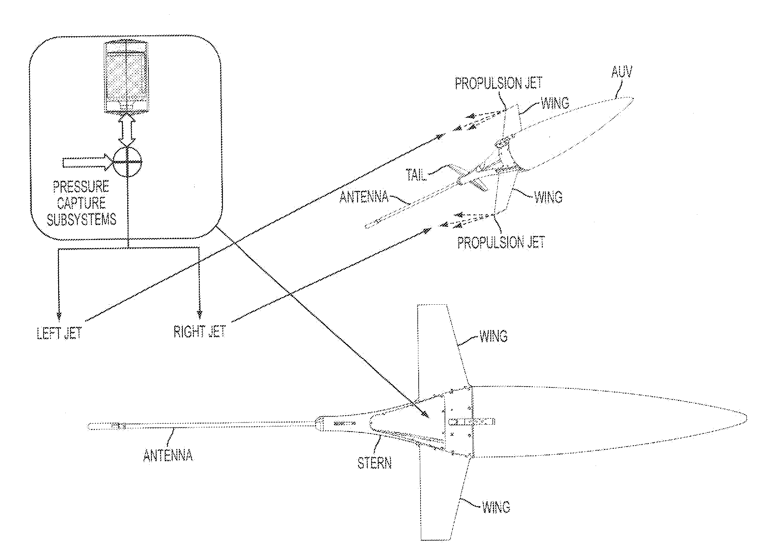
Air-Deployable UUV Platform for Sensors

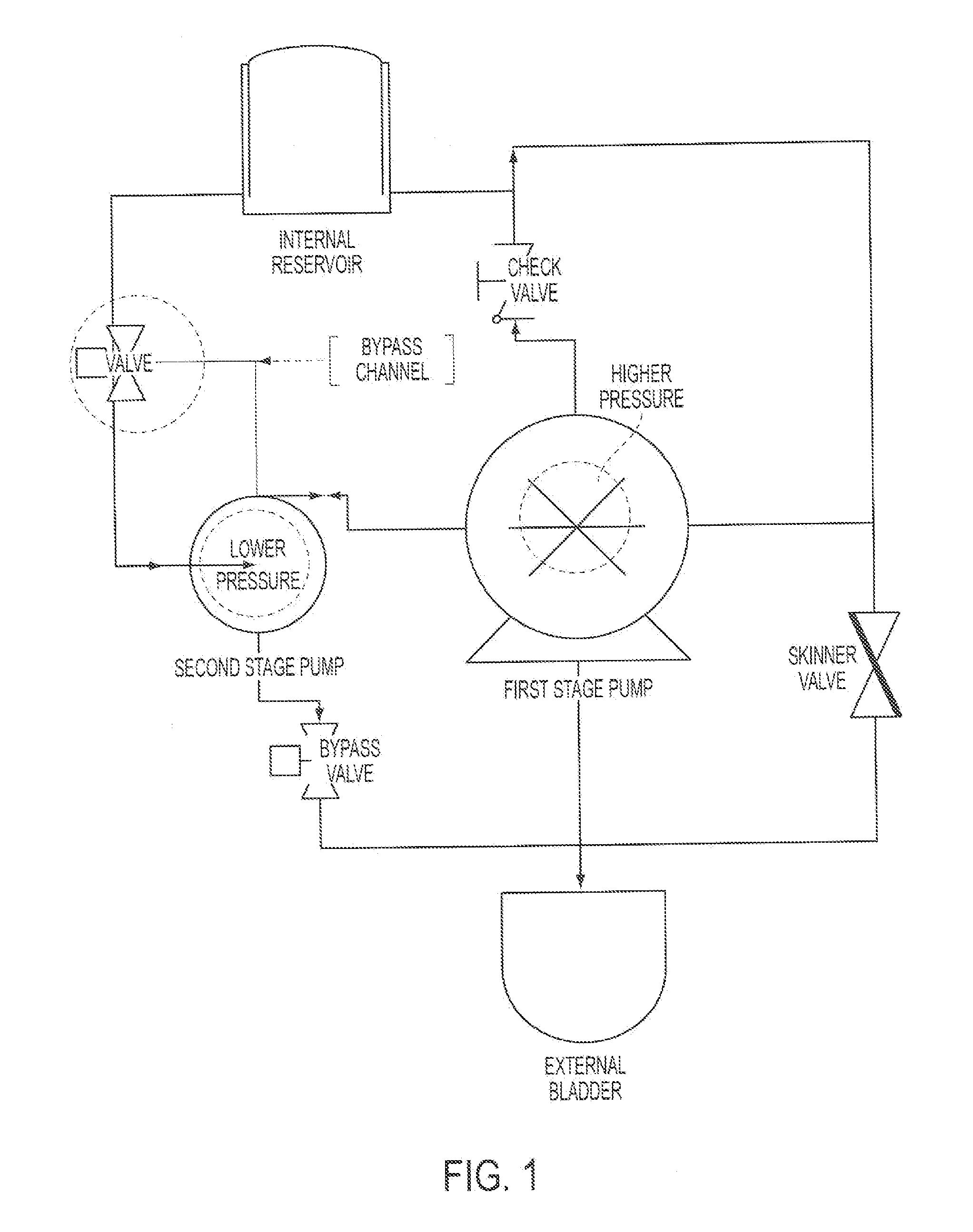
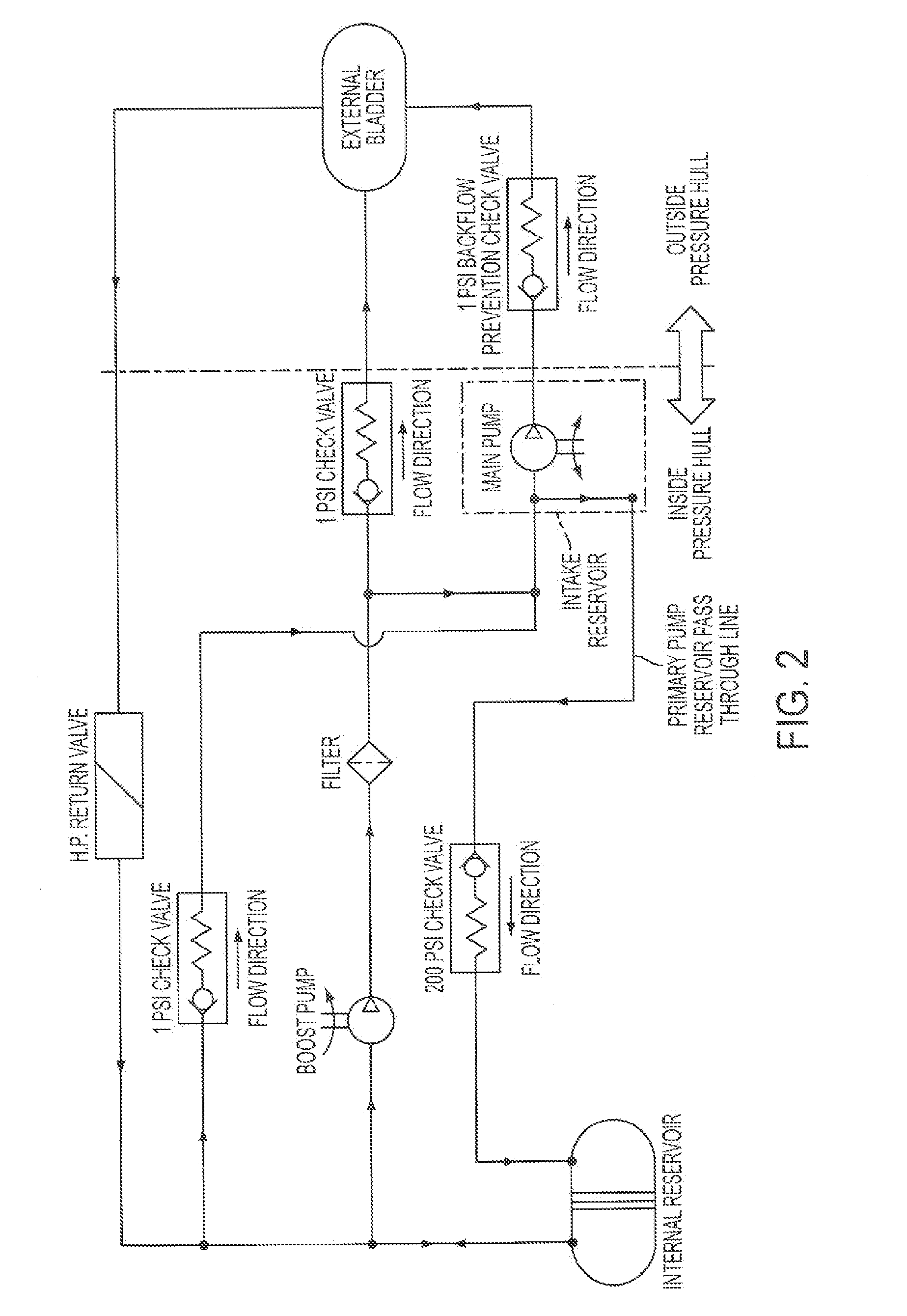
[0051]Reference will now be made in detail to the present teachings, exemplary embodiments of which are illustrated in the accompanying drawings. Embodiments of a UUV in accordance with the present teachings can employ methods proven in ocean gliders coupled to small form factor UUV's to provide a system with exceptional duration and mission flexibility. Embodiments of the present teachings that include a substantially “A” sized design will be air deployable using existing sonobuoy launch systems fitted to existing and future airframes or unmanned air systems, allowing rapid, low logistic deployment to various operational locations. Embodiments of the present teachings provide a method to convert the buoyancy and distribution of mass status of a UUV from a status that is efficient at low energy loitering and station keeping to a status that can be propelled either at low speeds for tactical insertion, or at high speeds for pursuit of contacts o...


PUM


Abstract

An hybrid unmanned underwater vehicle comprises a body housing a controller; a vector thruster for propelling the body; deployable wings allowing the unmanned underwater vehicle to traverse by gliding as the unmanned underwater vehicle ascends and descends; a center-of-mass shifter for shifting a center-of-mass of the vehicle to allow the unmanned underwater vehicle to pitch up and pitch down; and one of a multi-stage buoyancy control system within the body and configured to adjust an apparent displacement of the unmanned underwater vehicle and an expandable outer shell configured to adjust an apparent displacement and therefore a buoyancy of the unmanned underwater vehicle.

Description

INTRODUCTION[0001]This application is a continuation-in-part of U.S. patent application Ser. No. 12 / 890,584, filed Sep. 24, 2010, for an Autonomous Underwater Vehicle. This application claims priority to U.S. patent application Ser. No. 13 / 038,373, filed Mar. 1, 2011, for an Underwater Vehicle Buoyancy System. This application also claims priority to U.S. Provisional Patent Application No. 61 / 497,013, filed Jun. 14, 2011, for an Unmanned Underwater Glider. Each of these references is incorporated herein by reference in its entirety.[0002]The present teachings relate to unmanned underwater vehicles. The present teachings relate more particularly to hybrid unmanned underwater vehicles that can perform a variety of behaviors that increase endurance and mission capability.BACKGROUND[0003]A conventional unmanned underwater vehicle (“UUV,” also referred to herein as an autonomous underwater vehicle (“AUV”)), travels via powered propulsion and mostly travels in a horizontal direction. Dept...

Claims


Application Information

Patent Timeline
15 Nov 2012
Publication
US20120289103A1
IPC
B63G8/22; H02K7/18; B63H11/00
CPC
F42B19/00; B63J2003/006; F42B19/04; F42B19/06; F42B19/12; B63G8/001; B63J3/04; B63G8/08
Inventors
HUDSON, EDISON THURMAN; LICHT, STEPHEN CARL