Tissue imaging system and in vivo monitoring method

Active Publication Date: 2012-11-15
FUJIFILM CORP
View PDF5 Cites 27 Cited by
  • Summary
  • Abstract
  • Description
  • Claims
  • Application Information

AI Technical Summary

Benefits of technology

[0008]In view of the foregoing problems, an object of the present invention is to provide a tissue imaging system and in vivo monitoring method in which oxygen saturati

Problems solved by technology

Measuring light from the non-contact measurement probe cannot be sufficiently applied to the b

Method used


Image

  • Tissue imaging system and in vivo monitoring method
  • Tissue imaging system and in vivo monitoring method
  • Tissue imaging system and in vivo monitoring method

Examples


Example

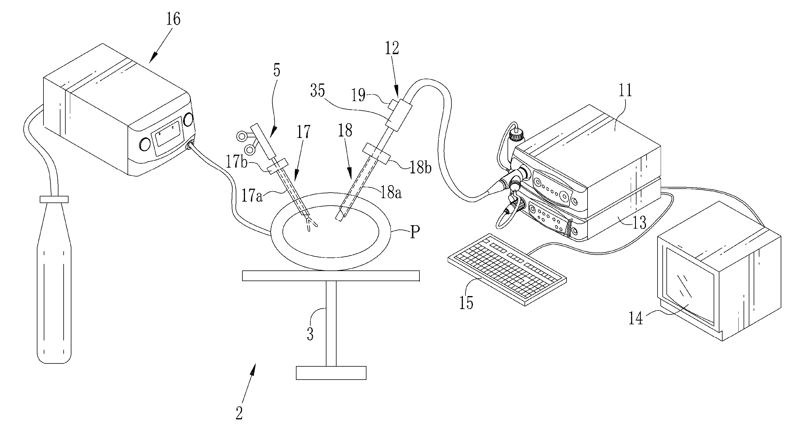
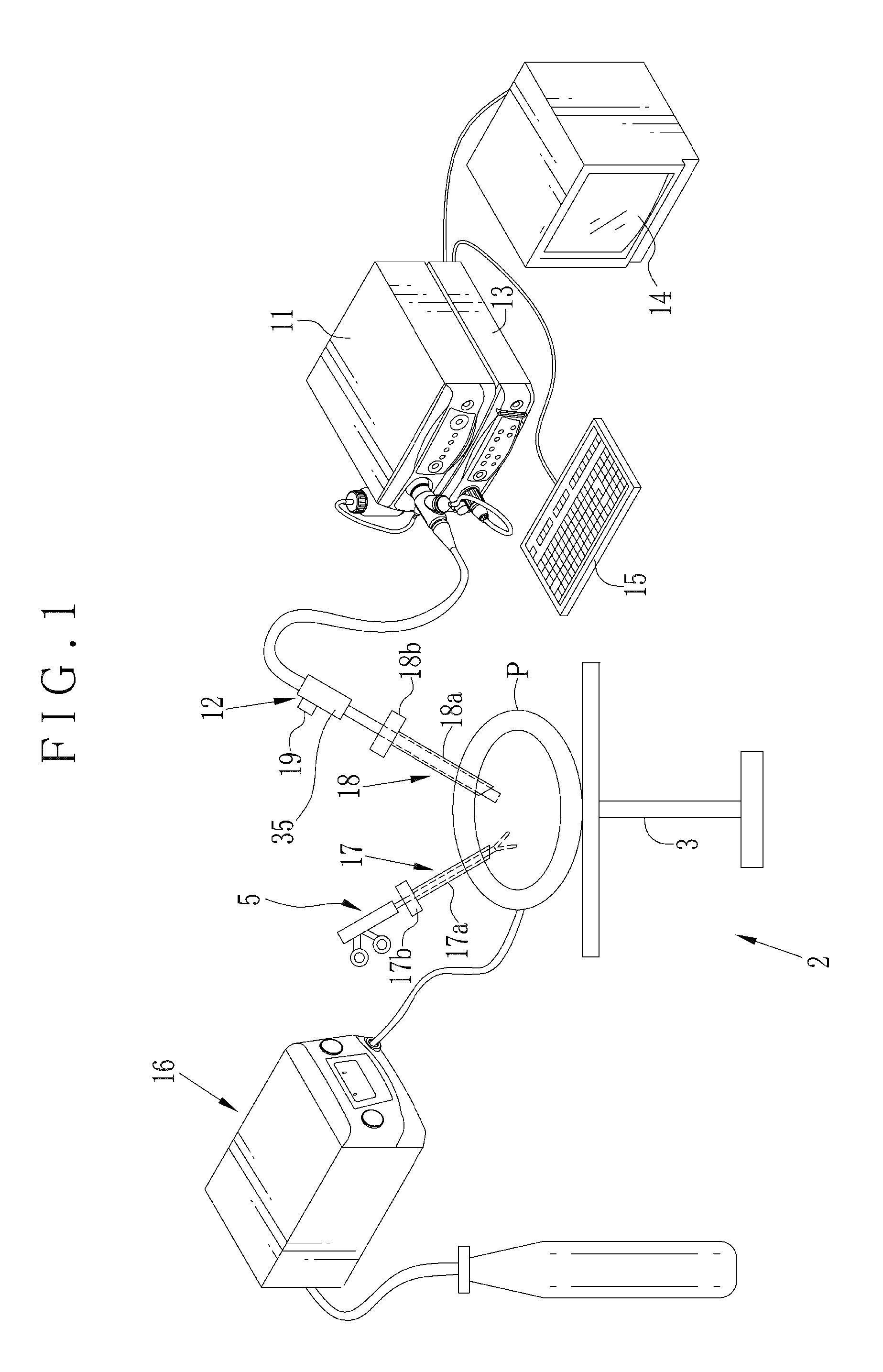
[0051]In FIG. 1, a laparoscope system 2 as tissue imaging system is illustrated. A body of a patient P lies on an operating table 3. A laparoscope 12 is entered in a body cavity of the body for imaging body tissue as a target of percutaneous treatment (laparoscopic surgery). An electrocautery device 5 or other medical instruments are used for the treatment. The laparoscope system 2 includes an illumination apparatus 11, the laparoscope 12, a processing apparatus 13 and a display panel 14 as display unit. The illumination apparatus 11 emits light of a predetermined wavelength range. The laparoscope 12 has optics for guiding the light to the body tissue, and also detects object light reflected by the body tissue. The processing apparatus 13 processes an image signal from the laparoscope 12. The display panel 14 displays the image after the image processing. An insufflator 16 supplies the body cavity with carbon dioxide gas for maintaining a space for viewing and treatment.

[0052]Trocar...


PUM


Abstract

An in vivo monitoring method in a laparoscope system is provided. An object image is sequentially created with expression of a surface color of an object in a body cavity. A lock area (specific area) is determined within the object image, the lock area being movable by following motion of the object. A monitor image including a graph of oxygen saturation is generated according to a part image included in the object image and located in the lock area. The monitor image is displayed. Preferably, the oxygen saturation of the lock area is acquired according to two spectral data with respect to wavelengths of which an absorption coefficient is different between oxidized hemoglobin and reduced hemoglobin in data of the object image. The object is constituted by a blood vessel.

Description

BACKGROUND OF THE INVENTION[0001]1. Field of the Invention[0002]The present invention relates to a tissue imaging system and in vivo monitoring method. More particularly, the present invention relates to a tissue imaging system and in vivo monitoring method in which oxygen saturation of body tissue in a body cavity is monitored with high stability even upon incidental shift of a field of view of an imaging instrument for imaging of by body tissue.[0003]2. Description Related to the Prior Art[0004]JP-A 2000-139947 discloses percutaneous treatment (laparoscopic surgery) of a patient's body by use of a laparoscope. In the percutaneous treatment, two or three holes are formed in skin outside an abdominal cavity. The laparoscope and a medical instrument for operation are inserted in the holes into the abdominal cavity. The abdominal cavity is insufflated with gas, such as carbon dioxide gas. A doctor or operator observes an image in the abdominal cavity by use of a monitor display panel,...

Claims


Application Information

Patent Timeline
IPC IPC(8): A61B5/1459A61B1/31A61B1/313A61B1/273A61B5/1455A61B6/00
CPCA61B1/0638A61B1/0653A61B1/3132A61B5/0075A61B1/0646A61B5/1459A61B1/00009A61B1/0005A61B1/063A61B5/14551A61B1/000094A61B1/0655
Inventor YAMAGUCHI, HIROSHI
Owner FUJIFILM CORP
Why Eureka
Try Eureka