Interposer films useful in semiconductor packaging applications, and methods relating thereto
What is AI technical title?
AI technical title is built by Patsnap AI team. It summarizes the technical point description of the patent document.
a technology of interposer film and semiconductor packaging, which is applied in the direction of transportation and packaging, synthetic resin layered products, coatings, etc., can solve the problems of interposer film exhibiting dimensional distortion
Inactive Publication Date: 2012-11-22
EI DU PONT DE NEMOURS & CO
View PDF0 Cites 43 Cited by
Summary
Abstract
Description
Claims
Application Information
AI Technical Summary
This helps you quickly interpret patents by identifying the three key elements:
Problems solved by technology
Method used
Benefits of technology
Benefits of technology
The present disclosure is about a special film used in IC packaging that has conductive domains supported by a thin substrate. The substrate is made from a special polyimide material that has been made from a combination of dianhydride and diamine components. The film also contains a small amount of a filler that is smaller than 550 nanometers and has a specific shape. The technical effect of this invention is to provide a more efficient and reliable interposer film for IC packaging.
Problems solved by technology
In such packaging applications, processing temperatures can at times be very high, e.g., above 300° C. At such high operating temperatures the interposer film can exhibit dimensional distortion.
Also, attempts to decrease processing costs can require reel-to-reel operations at increasingly higher tensions and such high tensionprocessing can also cause an interposer film to exhibit dimensional distortion.
Method used
Image
Click on the blue label to locate the original text in one second.
Reading with bidirectional positioning of images and text.
Examples
example 1
15 vol % (34.3 wt %) Acicular TiO2 in PMDA / / ODA
[0118]25.0 grams of acicular TiO2 (FTL-110, Ishihara Corporation, USA) was combined with 141.11 grams of anhydrous DMAC. This slurry was mixed at high shear for approximately 10 to 15 minutes using Silverson Model L4RT high-shear mixer (Silverson Machines, LTD, Chesham Baucks, England) equipped with a square-hole, high-shear screen (with a blade speed of approximately 4000 rpm).
[0119]In a round bottom flask, 74.1 grams of the slurry containing acicular TiO2 was mixed with 116.94 grams of PMDA / / ODA prepolymer (20 wt % solution in anhydrous DMAC), and the resulting mixture was stirred for approximately 24 hours. During this operation, a gentle nitrogen gas purge was used in the round bottom flask.
[0120]After stirring for approximately 24 hours, this material was filtered through 45 micron filter media (Millipore, 45 micron polypropylene screen, PP4504700).
[0121]In a separate container, a 6 wt % solution of pyromellitic anhydride (PMDA) wa...
example 2
10 vol % (24.70 wt %) Acicular TiO2 (FTL-110) in PMDA / / ODA
[0135]The same procedure as described in Example 1 was followed, with the following exceptions. 54.24 grams of the slurry containing acicular TiO2 (FTL-110, 15 wt % in DMAC) was mixed with 136.15 grams of PMDA / / ODA prepolymer (20 wt % in DMAC).
[0136]The material was finished with the PMDA solution to a viscosity of 899 poise.
[0137]CTE, E′ and % elongation at break were measured as in Example 1.
[0138]Results are shown in Table 1.
example 3
20 vol % (42.5 wt %) Acicular TiO2 (FTL-110) in PMDA / / ODA
[0139]The same procedure as described in Example 1 was followed, with the following exceptions. 57.7 grams of the slurry containing acicular TiO2 (FTL-110, 15 wt % in DMAC, high shear mixed) was combined with 63.3 grams of PMDA / / ODA prepolymer (20.6 wt % in DMAC).
[0140]The material was finished with the PMDA solution to a viscosity of 1380 poise.
[0141]CTE, E′ and % elongation at break were measured as in Example 1.
[0142]Results are shown in Table 1.
PUM
Property
Measurement
Unit
thickness
aaaaa
aaaaa
volume percent
aaaaa
aaaaa
temperatures
aaaaa
aaaaa
Abstract
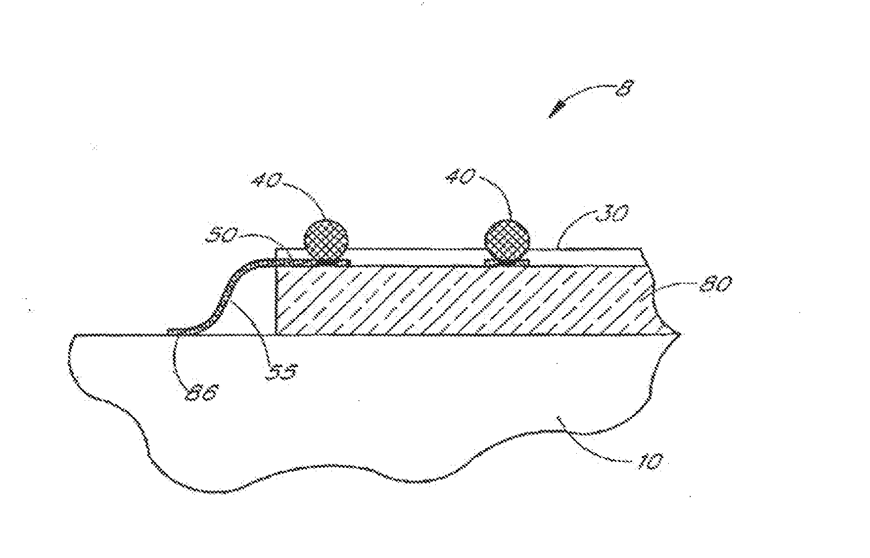
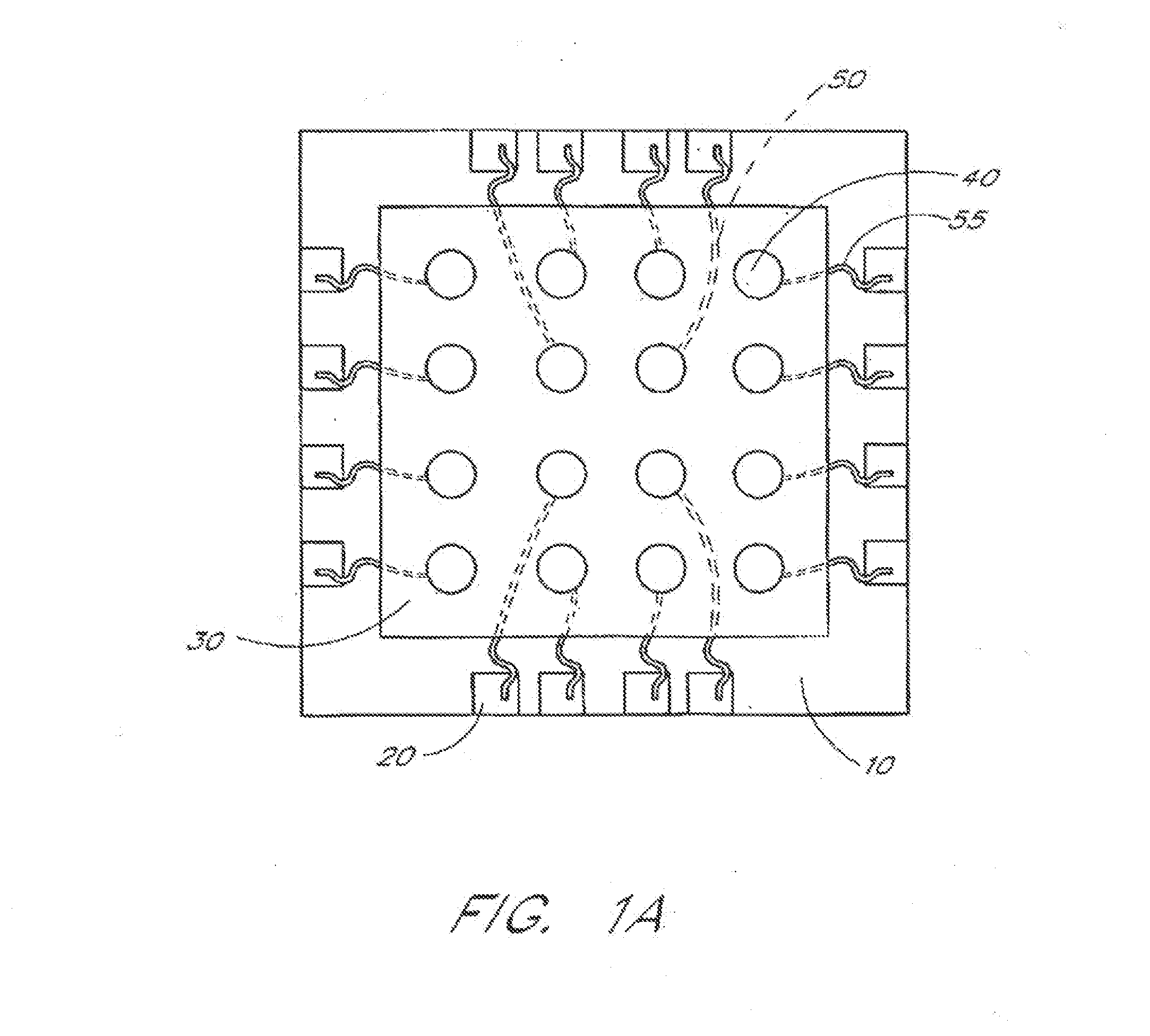
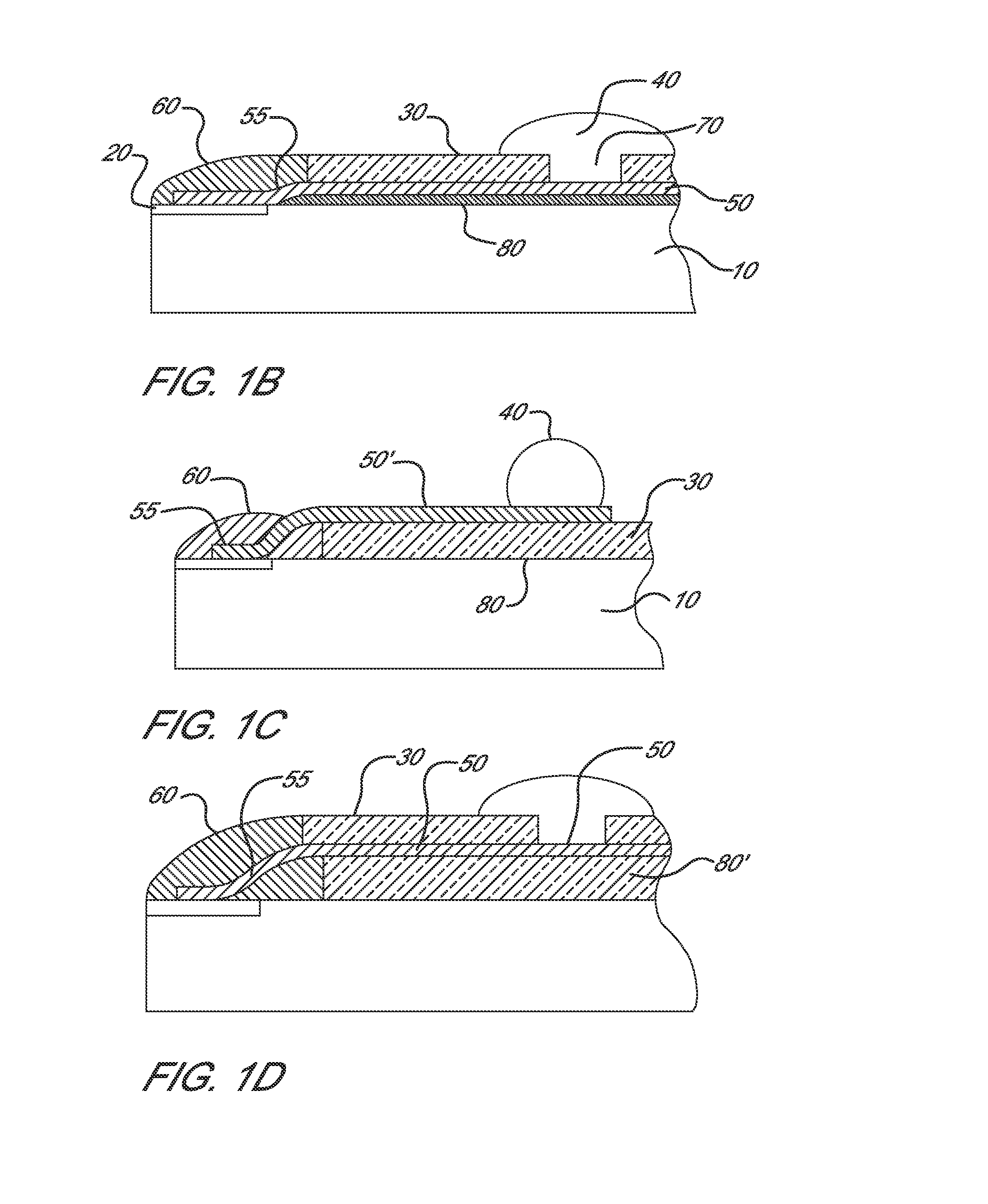
An interposer film for IC packaging is disclosed. The interposer film comprises a substrate that supports a plurality of electrically conductive domains. The substrate is composed of a polyimide and a sub-micron filler. The polyimide is derived from at least one aromatic dianhydride component selected from rigid rod dianhydride, non-rigid rod dianhydride and combinations thereof, and at least one aromatic diamine component selected from rigid roddiamine, non-rigid rod diamine and combinations thereof. The mole ratio of dianhydride to diamine is 48-52:52-48 and the ratio of X:Y is 20-80:80-20 where X is the mole percent of rigid rod dianhydride and rigid rod diamine, and Y is the mole percent of non-rigid rod dianhydride and non-rigid rod diamine. The sub-micron filler is less than 550 nanometers in at least one dimension; has an aspect ratio greater than 3:1; is less than the thickness of the film in all dimensions.
Description
FIELD OF DISCLOSURE[0001]The present disclosure relates generally to an interposer film for integrated circuit packaging comprising a plurality of electrically conductive domains supported by a substrate. More specifically the substrate is a polyimide film comprising a sub-micron filler and a polyimide having a hybrid backbone structure.BACKGROUND OF THE DISCLOSURE[0002]IC packaging technology is applied to IC chips: (1) to provide a path for the electrical current that powers the circuits on the chip; (2) to distribute the signals on to and off of the chip; (3) to remove the heat generated directly or indirectly by the IC chip; and (4) to support and protect the chip from hostile environments. A typical ball grid array (BGA) IC package includes an IC chip affixed to a flexible polyimide interposer film. In such BGA type IC packaging applications, a thin wire bond is used to connect a pad on the IC chip to a conductive trace on the polyimide interposer film. The conductive trace is ...
Claims
Application Information
Patent Timeline
Application Date:The date an application was filed.
Publication Date:The date a patent or application was officially published.
First Publication Date:The earliest publication date of a patent with the same application number.
Issue Date:Publication date of the patent grant document.
PCT Entry Date:The Entry date of PCT National Phase.
Estimated Expiry Date:The statutory expiry date of a patent right according to the Patent Law, and it is the longest term of protection that the patent right can achieve without the termination of the patent right due to other reasons(Term extension factor has been taken into account ).
Invalid Date:Actual expiry date is based on effective date or publication date of legal transaction data of invalid patent.
Patent Type & AuthorityApplications(United States)

