
Stationary concentrated solar power module

a solar power module and concentrated technology, applied in the field of solar power, can solve the problem of no optically “dead zones”, achieve the effects of reducing wavefront error, constant and high-efficiency operation, and improving system performance and physical (structural) reliability

Inactive Publication Date: 2012-12-13
FARBEROV ARKADIY
View PDF6 Cites 10 Cited by
  • Summary
  • Abstract
  • Description
  • Claims
  • Application Information

AI Technical Summary

Benefits of technology

[0014]An object of the invention is to provide a design that does not need a tracking unit to constantly follow the sun but nonetheless ensures constant and highly efficient operation throughout an entire day. An additional object of the invention is to replace the Fresnel lenses with concentration lenses that would act in the same capacity as the tracking units but that would be structurally simple and that would not have mechanically moving parts. The use of freeform lenses enables one to meet these requirements. In addition, freeform lenses do not contain microprisms; their surface, although highly curvilinear, is quite smooth, and therefore no optically “dead zones’ are likely. These two major improvements in the concentration module design, namely, use of a tracking-free unit and Fresnel-lens-free photovoltaic devices, wherein each optical module consists of a single concentration lens and a plurality of cells sequentially arranged on the path of the light beam, are expected to result in significantly higher functional (optical) performance and physical (structural) reliability of the system.
[0015]In other words, the invention makes it possible to get rid of a tracking unit by making the location (placement) of the solar cells dependent on the incident angle of the incident solar rays. In the context of the invention, the incident angle is an angle of solar rays relative to the optical axis of the concentrator lens. In an immovable lens, displacement of the illuminated spot depends on the aforementioned incident angle. The illuminated spot moves along a particular trajectory. If one places the solar cells along this trajectory, then operation of the concentrator becomes possible without resorting to the need of a tracking unit. Replacement of the Fresnel lenses in light-concentration devices with free-form lenses is another important change in the existing technology. As known, a free-form optical surface is defined as a nonrotationally symmetric surface or as a symmetric surface that rotates about any axis that is not its axis of symmetry. Such free surfaces offer additional “degrees of freedom” that can be used to obtain a significantly lower wavefront error and a smaller-size device, as compared to rotationally symmetric surfaces. A free-form surface is a complex, irregular, asymmetric and aspheric surface. Free-form optics includes rotationally symmetric elements such as aspheric and parabolic. It is noteworthy that such components using free-form optical surfaces are quite common in some state-of-the-art optical instruments. Free-form lenses are effective optical concentrators that are able to ensure optimal illumination and reliable operation (functional, structural, and environmental) of a photovoltaic unit. Free-form optical surfaces embedded in a three-dimensional space, without any symmetry, could be designed (“tailored”) in such a way that they would be able to solve the original archetypal problem of an illumination design, which is to redistribute the radiation from a given light source onto a given reference surface to achieve the desired (“prescribed”) irradiance distribution on that surface. An important advantage of the free-form concept is the ability to properly co-locate the distant optical center and the near-distant optical center.

Problems solved by technology

In addition, freeform lenses do not contain microprisms; their surface, although highly curvilinear, is quite smooth, and therefore no optically “dead zones’ are likely.

Method used


Image

  • Stationary concentrated solar power module
  • Stationary concentrated solar power module
  • Stationary concentrated solar power module

Examples


Embodiment Construction

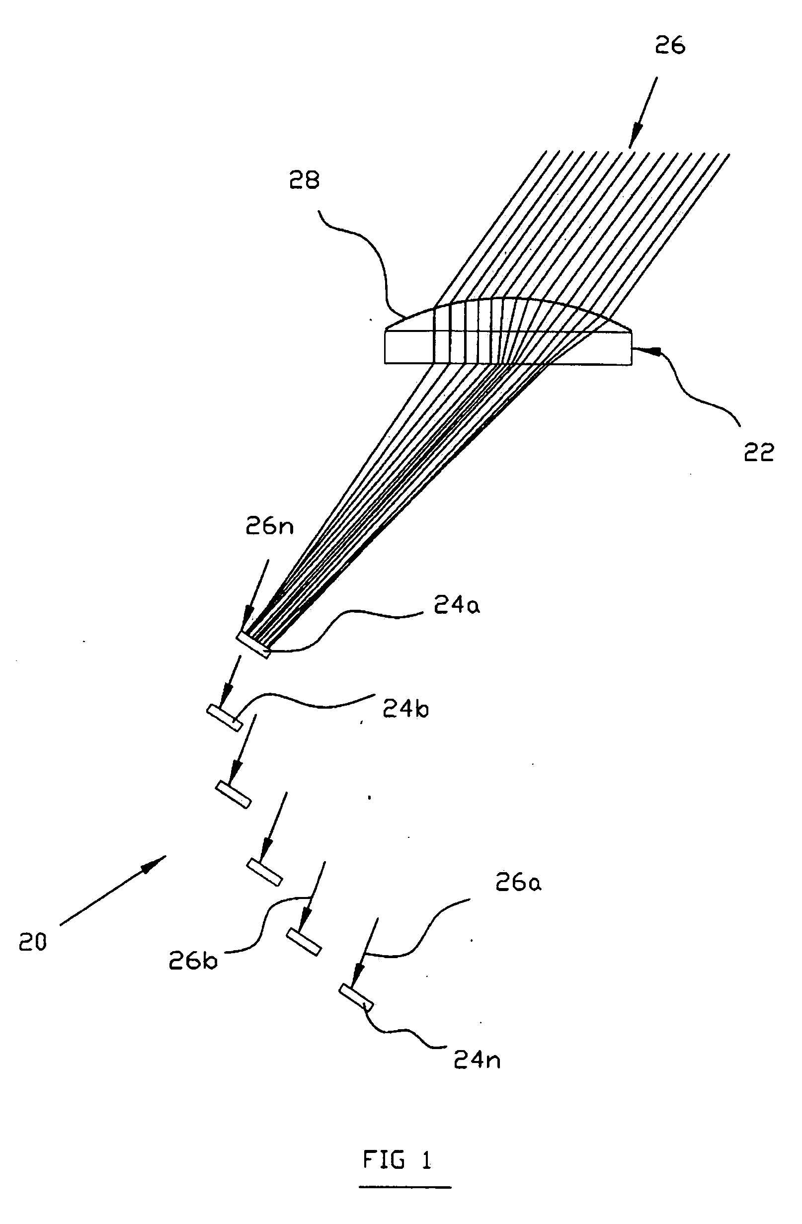
[0030]In a most simplified and generalized form, the CPS solar module of the present invention is schematically shown in FIG. 1. The module, which as a whole is designated by reference numeral 20, consists of a focusing lens 22 and a plurality of individual solar cells 24a, 24b, . . . 24n. When the lens 22 is immovable (does not change its position), the solar rays 26 fall on its receptive surface 28 at different angles, depending on the time of day and the angular velocity of the Earth around its axis. At each moment, a particular location (coordinate) of the illuminated zone depends on the geometric characteristics of the concentrated lens 22. The illuminated spots (not shown in FIG. 1), at which the solar cells 24a, 24b, . . . 24n should be placed, move along a certain trajectory, taking sequential positions 26a, 26b, . . . 26n. These positions correspond to the slope angles, e.g., of 10, 20, . . . 50 degrees, respectively.

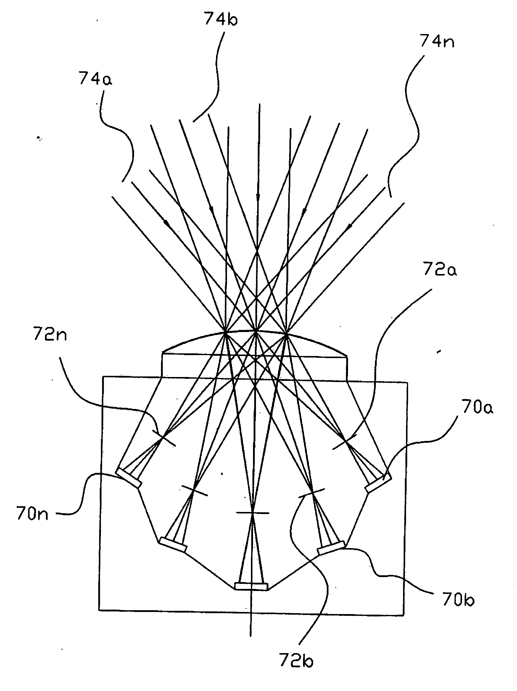
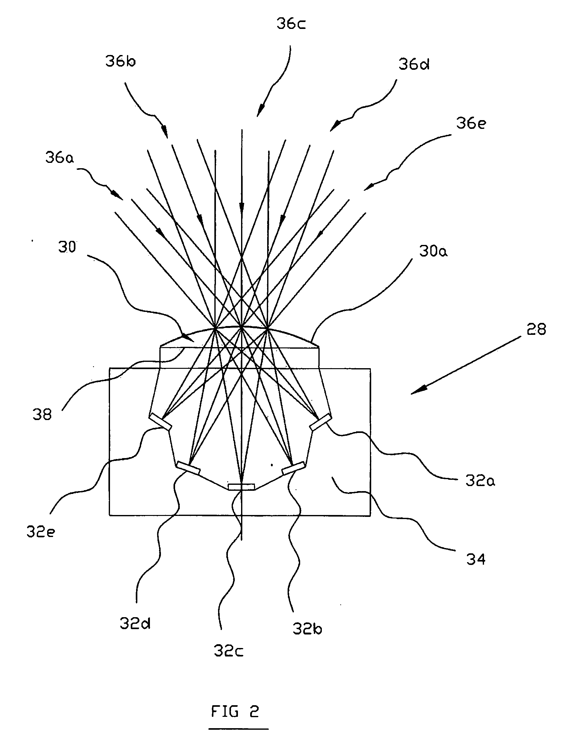
[0031]In FIG. 2 a CPS solar module 28 is shown in a more ...


PUM


Abstract

A stationary concentrated photovoltaic solar power module that is free of a tracking device and comprises a single optical lens and a plurality of photovoltaic solar cells spatially arranged on the track of a light spot produced on the photovoltaic solar cells by projection of the sun through the single optical lens unit. The cells are supported by the inner surface of the housing in the positions on the track of the light spot.

Description

FIELD OF THE INVENTION[0001]The present invention relates to the field of solar power and, more specifically, to a stationary concentrated photovoltaic solar module.BACKGROUND OF THE INVENTION[0002]The existing renewable energy photovoltaic devices include solar thermal devices, crystalline silicon devices, thin-film (amorphous silicon, CdTe, CIGS) devices, and concentrator devices. The latter are based on low- or high-concentration approaches. Concentrator devices, promising as they are, are still at the development stage, mostly because of their insufficient reliability for many applications. Today's concentrator photovoltaic solar (CPS) modules comprise three major components: (1) an optical concentrator (lens or mirror) that concentrates solar energy falling on the solar cell surface; (2) a solar cell (photovoltaic component) that converts light into electricity, and (3) a solar tracker (tracking unit) that is responsible for keeping the solar cells oriented toward the sun.[0003...

Claims


Application Information

Patent Timeline
Patent Type & Authority Applications(United States)
IPC IPC(8): H01L31/052
CPCH01L31/0543Y02E10/52
Inventor FARBEROV, ARKADIY
Owner FARBEROV ARKADIY
Learn More