[0008]The present inventor has recognized the aforementioned disadvantages associated with conventional optical or photoelectric sensors and related sensing processes, and has further recognized that the implementation of a
phosphor-based layer in relation to an optical /
photoelectric sensor (for example, within a
transmitter or
receiver of such a sensor) can allow for enhanced sensor performance in which one or more of such disadvantages are entirely or at least partly overcome.
[0009]In at least some embodiments, a method for reducing
optical noise includes, a first light having a selected wavelength from a
light source, receiving a reflected first light onto a phosphor-based layer positioned inside a receiver, the reflected first light being at least some of the emitted first light that has been reflected by an object positioned outside of a desired target location. The method further includes shifting the wavelength of the received reflected first light due to an interaction between the received reflected first light and the phosphor-based layer, and passing the received reflected first light with respect to which the wavelength has been shifted through a
light detector without detection. Further, in at least some embodiments, the phosphor-based layer includes at least one of a nano-phosphor and
quantum dot phosphors.
[0010]In at least some other embodiments, a method for reducing optical noise includes, receiving a first light from a first light source, passing the first light through, or reflecting the first light at, a first phosphor-based layer, wherein due to the passing or reflecting at least one characteristic of at least one portion of the first light is modified. The method further includes receiving the at least one portion of the modified first light at a first
light detector, wherein the at least one portion is received but not does not substantially influence an output of the first light
detector. Further, in at least some embodiments, the method additionally includes emitting a second light from a second light source, the second light having a first wavelength, receiving the second light at the first fight
detector subsequent to the second light being reflected by an object, and detecting the second light.
[0011]In at least yet some other embodiments, a method for reducing optical noise between devices includes, generating a first light from a first light source of a first
transmitter, passing the first light through a first phosphor based layer shifting the wavelength of the first light to a first selected wavelength, and emitting the shifted first light from the first transmitter. The method further includes, generating a second light from a second light source of a second transmitter, passing the second light through a second phosphor based layer, shifting the wavelength of the second light to a second selected wavelength, different than the first wavelength, and emitting the shifted second light from the second transmitter. Additionally, the method includes, receiving the shifted second light at the first receiver, passing the second light through a third phosphor-based layer shifting the wavelength of the second light to a wavelength that exceeds or substantially exceeds the detection range of first receiver, and passing the second light through the first receiver without detection.
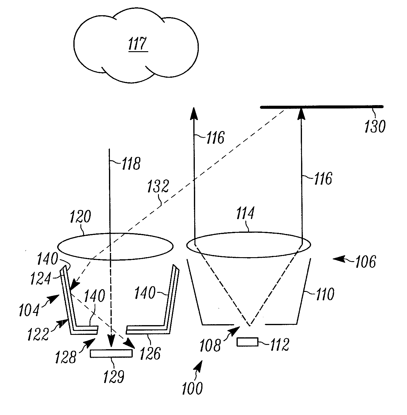
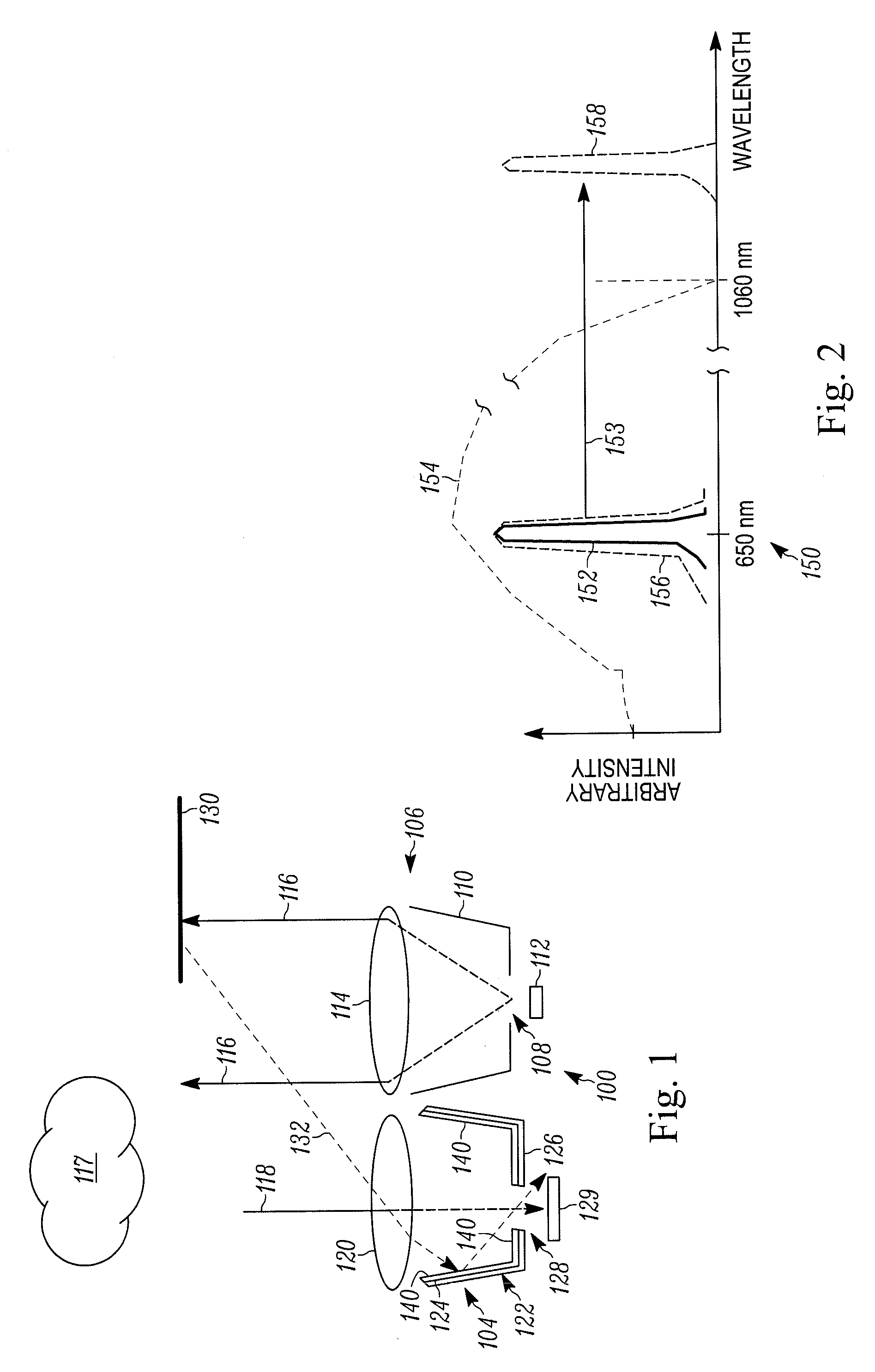
[0013]In at least yet still further embodiments, a
system for reducing optical noise includes, a transmitter having a light source for emitting first light at a pre-selected wavelength, a receiver having an optical housing and a light
detector, a receiver aperture positioned inside the receiver for receiving one or both of the first light and a second light and a phosphor-based layer situated inside the receiver for shifting the wavelength of one or both of the first and second light received into the receiver, to at least one wavelength value outside a wavelength detection range of the light detector.
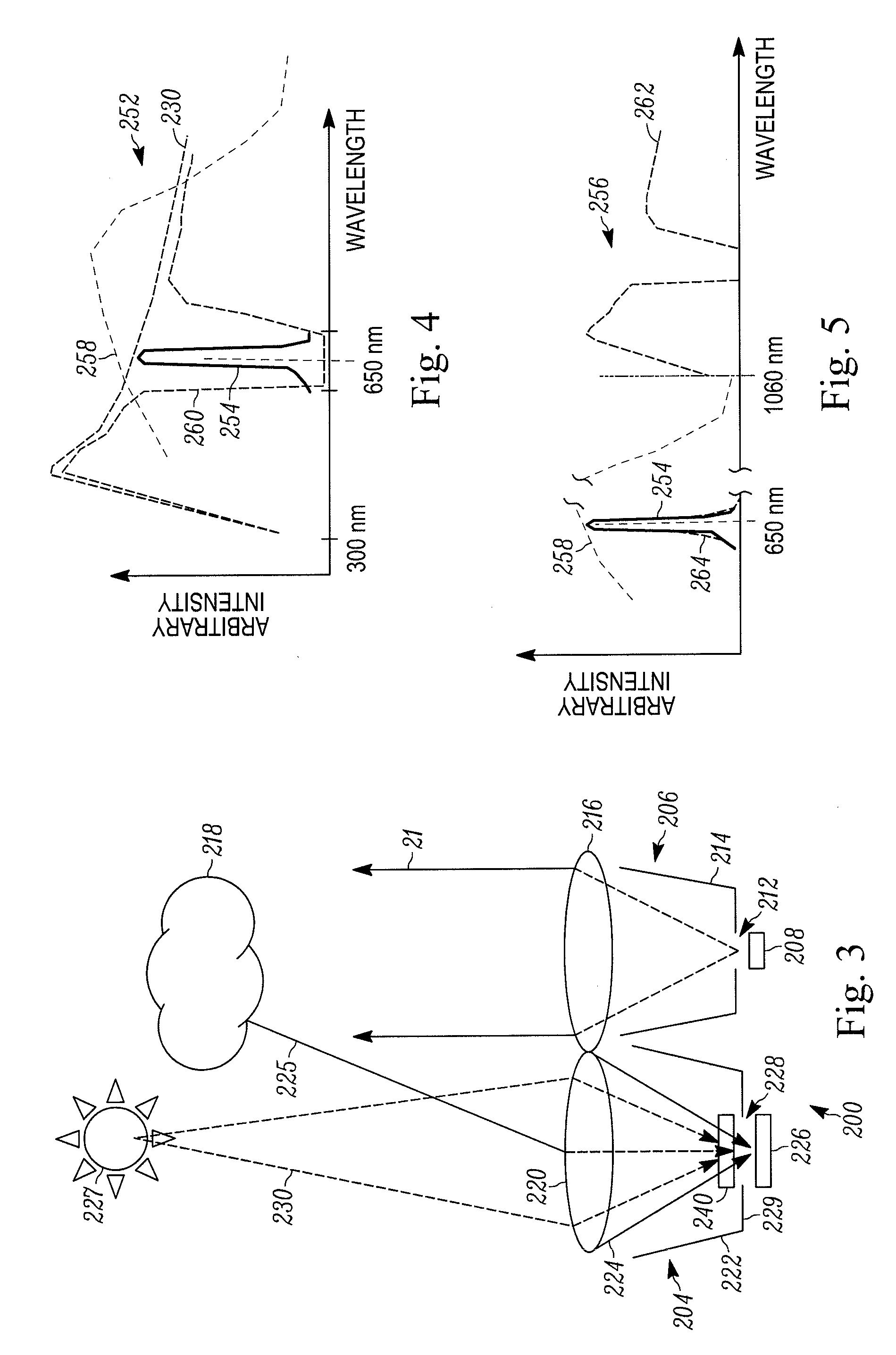
[0014]In at least yet still even further embodiments, a
system for reducing optical noise includes, a first transmitter having a first transmitter lens and a first optical housing with a first transmitter aperture, a first light source for emitting a multi-
colored first light, and a first phosphor-based layer positioned
proximate to the first transmitter aperture and between the first light source and the first lens. Additionally, the method can include a first receiver having a second phosphor-based layer and positioned to receive at least a portion of the multi-
colored first light, and a first light detector positioned in the first receiver, having multiple
colored pixels for sensing one or more of the colors in the multi-
colored light.

