Hydraulic pressure controller for continuously variable transmission

a continuously variable transmission and hydraulic pressure controller technology, applied in the direction of clutches, fluid couplings, gearing elements, etc., can solve the problems of oscillation of valve bodies, repetitive increase and decrease of belt tension, and lowering the durability of continuously variable transmission, so as to achieve the effect of more readily moving and moving

Inactive Publication Date: 2012-12-20
TOYOTA JIDOSHA KK
View PDF0 Cites 6 Cited by
  • Summary
  • Abstract
  • Description
  • Claims
  • Application Information

AI Technical Summary

Benefits of technology

[0022]That is, the valve body moves more readily when the driving hydraulic pressure is output as the temperature of the hydraulic oil increases. Further, after the driving hydraulic pressure is output, the timing at which the valve body starts to move in the valve closing direction is advanced as the temperature of the hydraulic oil increases.
[0023]Thus, after starting the output of the driving hydraulic pressure to the control valve to drive the valve body in the valve opening direction, it is preferred that a timing for further changing the driving hydraulic pressure be advanced as the temperature of the hydraulic oil increases. The employment of such a configuration allows for the timing for changing the hydraulic pressure to be set in accordance with changes in the responsiveness of the actual movement of the valve body relative to changes in the driving hydraulic pressure as the temperature of the hydraulic oil changes.
[0024]Further, as the hydraulic pr

Problems solved by technology

However, immediately after starting the driving of the valve bodies, inertia may excessively move the valve bodies and thereby oscillate the valve bodies.
When the hydraulic pressure supplied to each pulley oscillates, the tens

Method used


Image

  • Hydraulic pressure controller for continuously variable transmission
  • Hydraulic pressure controller for continuously variable transmission
  • Hydraulic pressure controller for continuously variable transmission

Examples


first embodiment

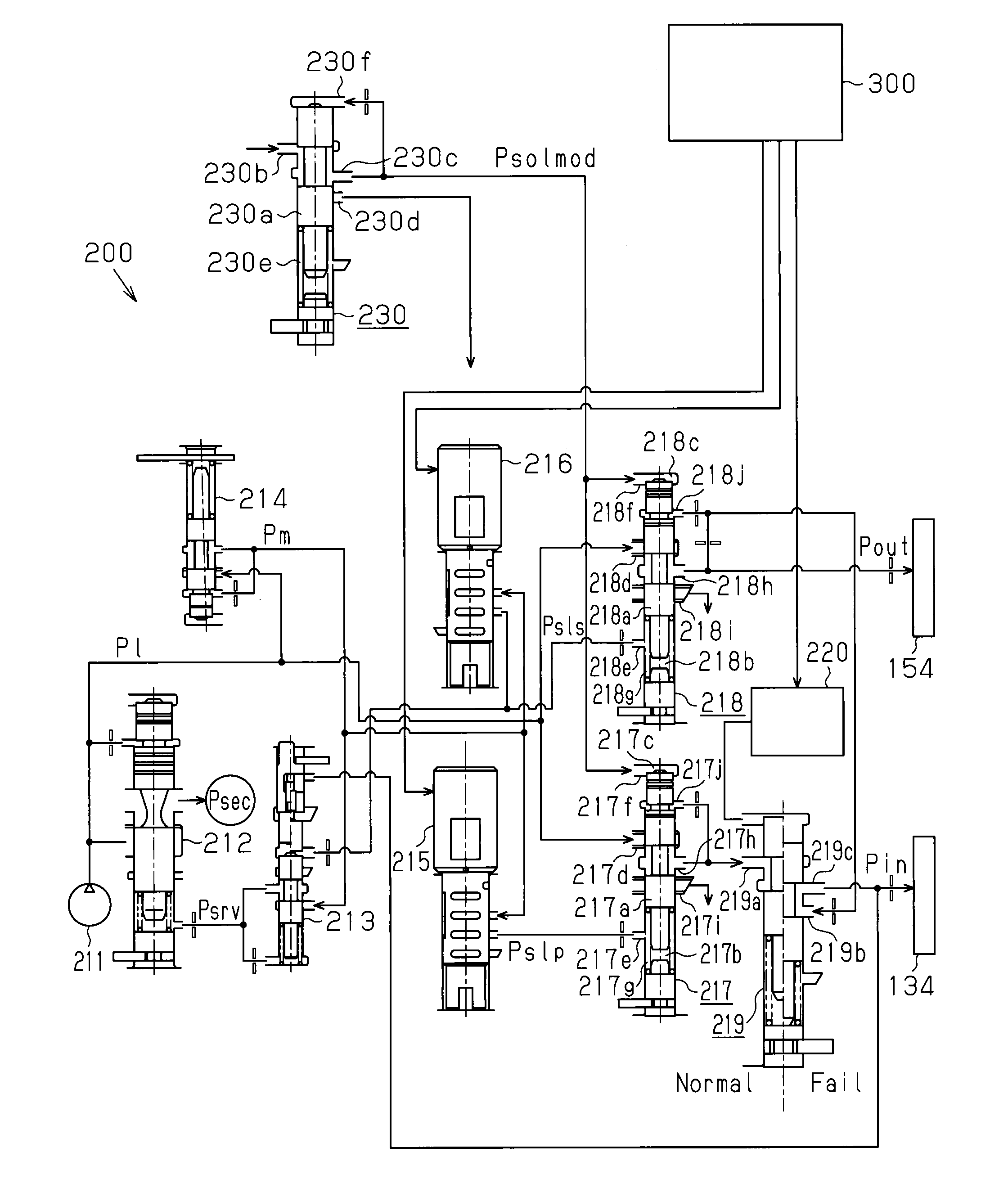
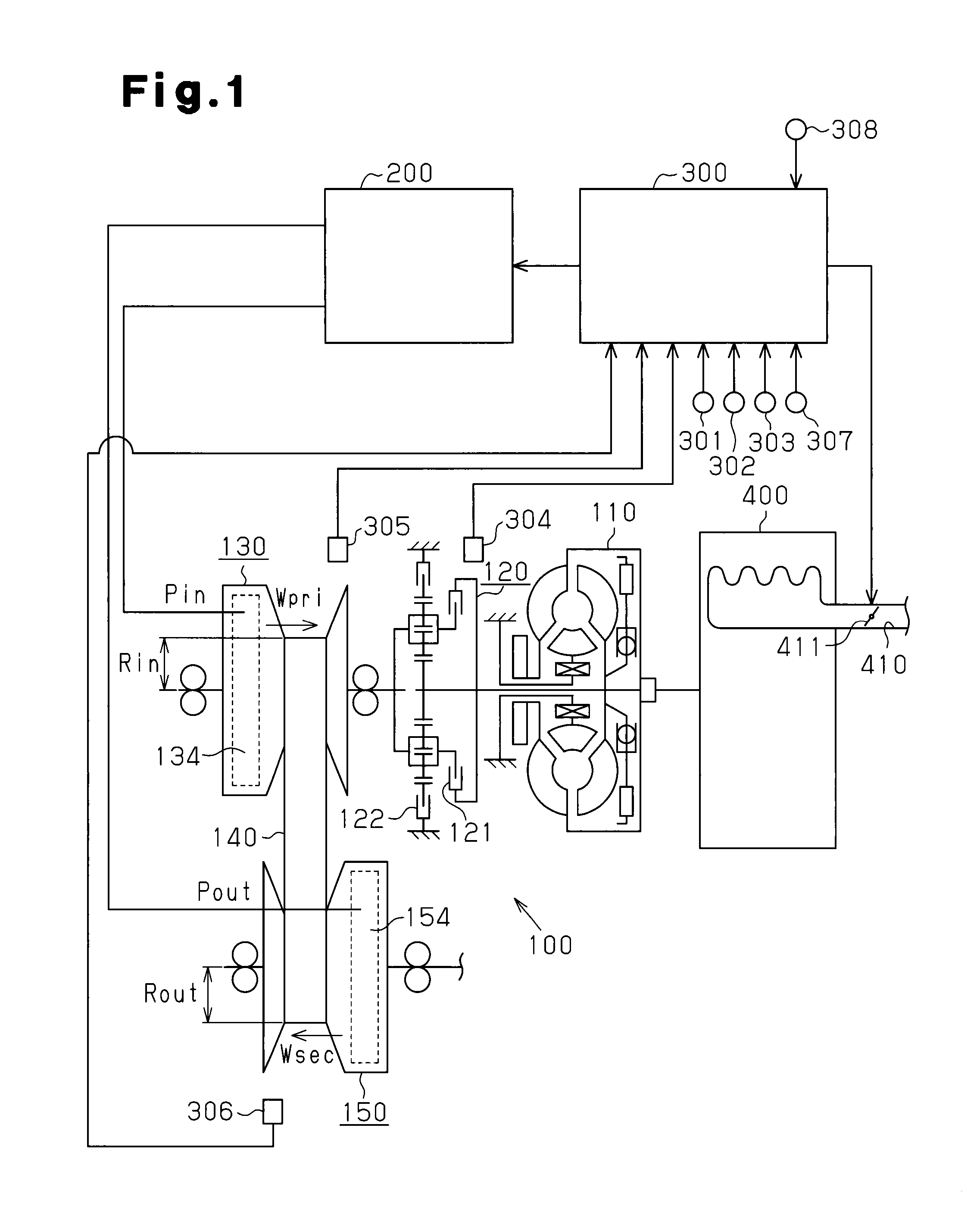
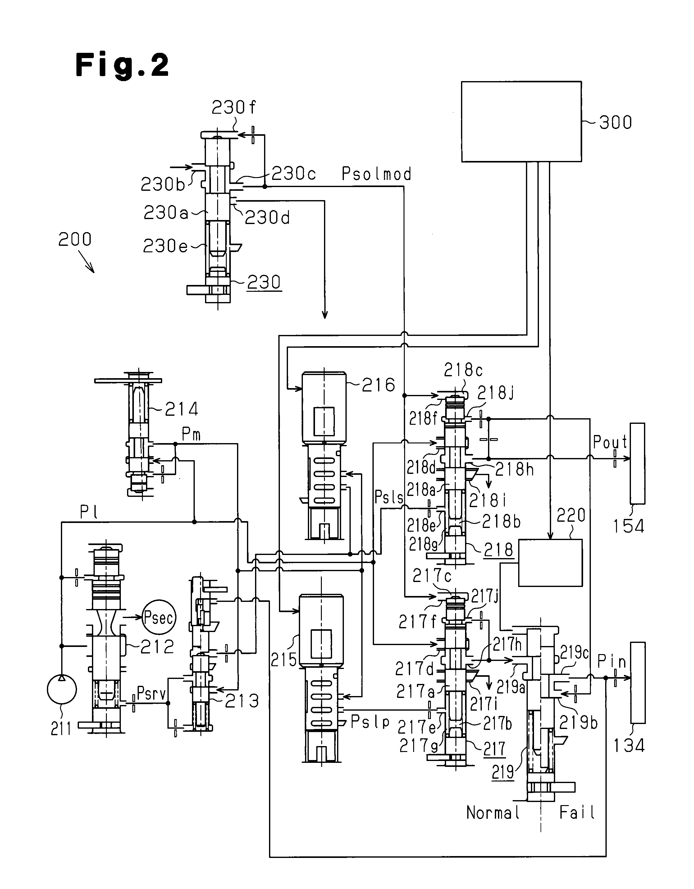
[0038]One embodiment of a hydraulic pressure controller for a continuously variable transmission according to the present invention applied to an electronic control unit 300 that controls a continuously variable transmission 100, which is installed in a vehicle, and a hydraulic pressure control unit 200 will now be described with reference to FIGS. 1 to 6.

[0039]FIG. 1 is a schematic diagram showing the structure of the continuously variable transmission 100, which is a control subject of the hydraulic pressure controller of the present invention.

[0040]As shown in FIG. 1, an input shaft of a torque converter 110 in the continuously variable transmission 100 is connected to an output shaft of an internal combustion engine 400. An output shaft of the torque converter 110 is connected to an input shaft of a switching mechanism 120.

[0041]The switching mechanism 120 is a double-pinion planet gear mechanism and includes a forward clutch 121 and a reverse brake 122. An output shaft of the s...

second embodiment

[0159]A second embodiment of a hydraulic pressure controller for a continuously variable transmission according to the present invention applied to an electronic control unit 300 that controls a continuously variable transmission 100, which is installed in a vehicle, and a hydraulic pressure control unit 200 will now be described with reference to FIGS. 7 and 8. The present embodiment differs from the first embodiment in that a closing valve 240 and a switching solenoid valve 241, which drives the closing valve 240, are added to the hydraulic pressure control unit 200, as shown in FIG. 7. Otherwise, the present embodiment is the same as the first embodiment. Thus, in the description hereafter, components that are the same as the first embodiment will not be described, and components differing from the first embodiment will be described in detail.

[0160]The hydraulic pressure control unit 200 of the present embodiment includes the closing valve 240 on the discharge passage through whi...


PUM


Abstract

Disclosed is a hydraulic control device for a continuously variable transmission which changes the transmission gear ratio by changing the hydraulic pressure (Pin, Pout) supplied to hydraulic pressure chambers (134, 154) for pulleys in the continuously variable transmission via control valves (217, 218) is changed. In this hydraulic control device, line pressure regulation hydraulic pressure (Psrv) which corresponds to the magnitudes of the oil pressure (Pin, Pout) supplied to the hydraulic pressure chambers (134, 154) is introduced into a regulator valve (212), and line pressure (P1) which is input into the control valves (217, 218) according to the magnitudes of the oil pressure (Pin, Pout) is subjected to feedback regulation. In the hydraulic control device for the continuously variable transmission, after the valve element (217a) of the control valve (217) is driven in the valve opening direction, a vibration restriction control operation which temporarily restricts the displacement of the valve element (217a) is executed.

Description

TECHNICAL FIELD[0001]The present invention relates to hydraulic pressure controllers for a continuously variable transmission that controls the hydraulic pressure supplied to each pulley of a belt type continuously variable transmission, and in particular, to a hydraulic pressure controller for a continuously variable transmission that feedback-adjusts a line pressure, which is an originating pressure of the hydraulic pressure supplied to each pulley, in accordance with the level of the hydraulic pressure supplied to each pulley.BACKGROUND ART[0002]A belt type continuously variable transmission is a known transmission mounted on a vehicle or the like. The belt type continuously variable transmission includes a first pulley that receives driving force from an internal combustion engine, a second pulley coupled to a vehicle wheel, and a belt running around the two pulleys. The continuously variable transmission changes the winding radius of the belt at each pulley to change the gear r...

Claims


Application Information

Patent Timeline
IPC IPC(8): F16D31/02
CPCF16H61/66272F16H61/66259F16H61/6625F16H2061/66286
Inventor NISHIDA, NAOFUMI
Owner TOYOTA JIDOSHA KK
Why Eureka
Try Eureka