
Application roller and manufacturing method of application roller

a manufacturing method and technology of application roller, applied in the direction of final product manufacturing, sustainable manufacturing/processing, cell components, etc., can solve the problems of reducing the service life of the battery, prone to failure of the masking film, fractures or wrinkles, etc., to reduce the edge thickness, increase the edge thickness, and increase the edge thickness

Active Publication Date: 2012-12-20
TOYOTA JIDOSHA KK
View PDF1 Cites 4 Cited by
  • Summary
  • Abstract
  • Description
  • Claims
  • Application Information

AI Technical Summary

Benefits of technology

[0009]The invention provides an application roller and a manufacturing method of the application roller adapted to apply a coating solution onto a substrate without wrapping a masking film therearound so that the increased edge thickness of the coating film can be reduced and that an edge position of the coating film is stabilized.
[0016]The above-described configurations negates the need for wrapping the masking film around the roller when the coating solution is applied onto the substrate. Furthermore, the coating film can be reduced in the increased edge thickness. That is, the coating film formed by applying the coating solution onto the substrate is prevented from having a greater thickness near an edge thereof than a thickness at a central portion thereof so that the coating film is reduced in the difference in thickness (increased edge thickness) between the central portion and the edge portion thereof. In addition, the edge position of the coating film is stabilized.

Problems solved by technology

However, inflow of hot air for drying the paste is likely to cause migration in which the binder resin is liberated from the active material in the applied paste and segregated in a depth direction of the applied paste.
When used in excess, however, the binder resin may interfere with the migration of lithium ions, impairing battery characteristics.
However, the coating technique described in JP 5-15824 A has the following problems.
However, since the masking film is in friction contact with the outer periphery of the application roller being rotated, the masking film is prone to failure such as fractures or wrinkles if the masking film is made too thin.
This leads to a problem that a coating film W formed by applying the coating solution P onto a substrate K has a greater thickness H1 near an edge WE thereof than a thickness H2 at a central portion WC thereof, as shown in FIG. 8.
According to the coating technique disclosed in JP 5-15824 A, the masking film is simply wrapped around the application roller and hence, the position of the masking film relative to the application roller is unstable.
This results in another problem that the coating film formed by applying the coating solution onto the substrate is varied in its edge position.

Method used


Image

  • Application roller and manufacturing method of application roller
  • Application roller and manufacturing method of application roller
  • Application roller and manufacturing method of application roller

Examples


Embodiment Construction

[0027]An application roller and a manufacturing method of the application roller according to an embodiment of the invention will be described in detail with reference to the accompanying drawings. Now, description is made on a resin laminating step, a masking forming step and an application groove forming step in the order named. In the explanation of the individual steps, a structure of the application roller is also described as needed.

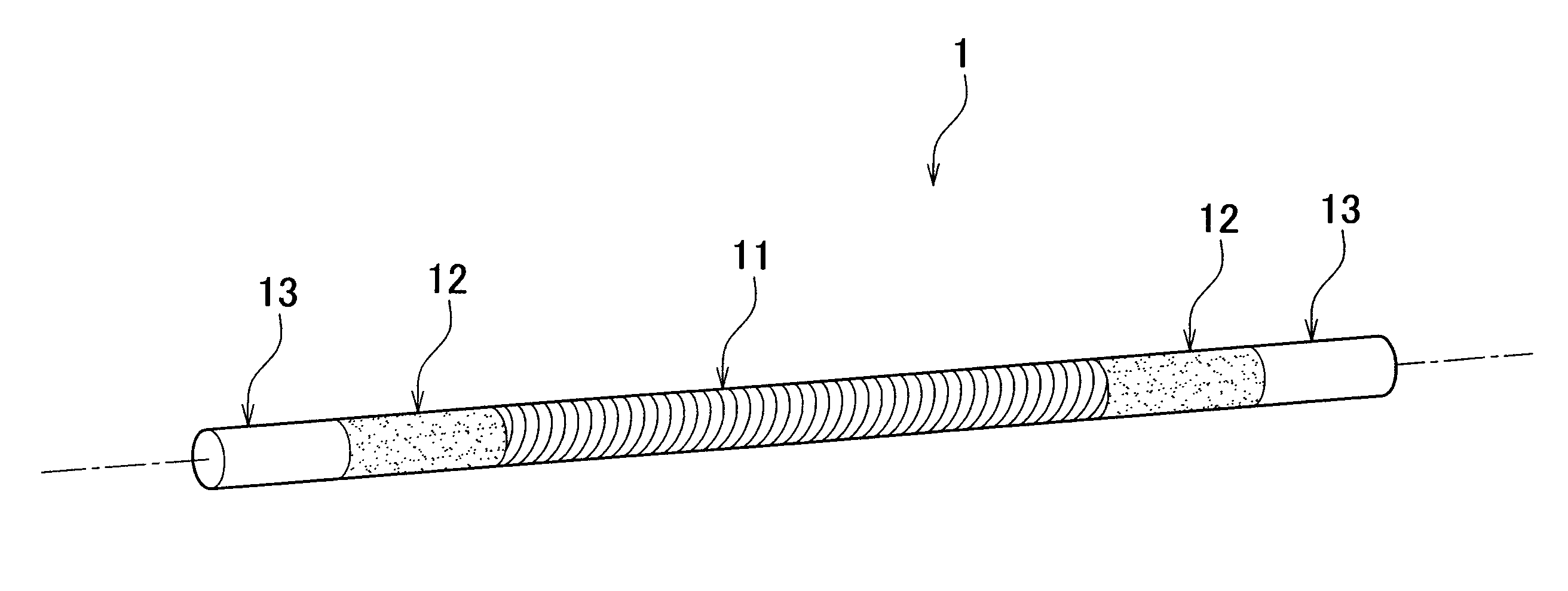
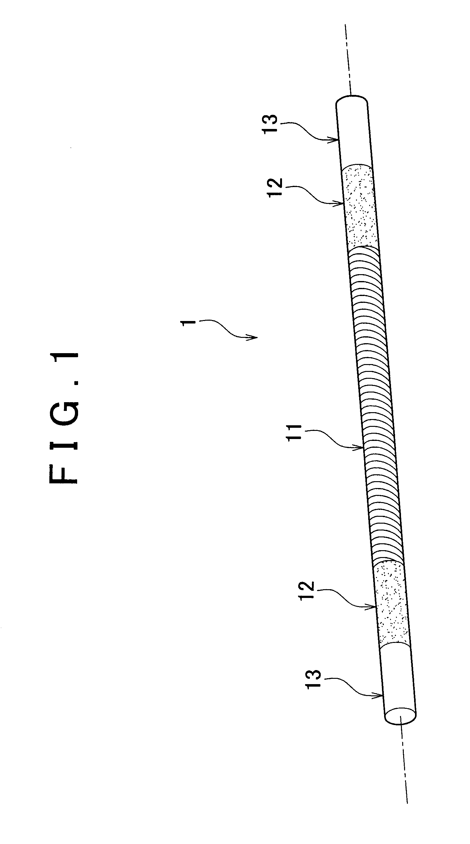
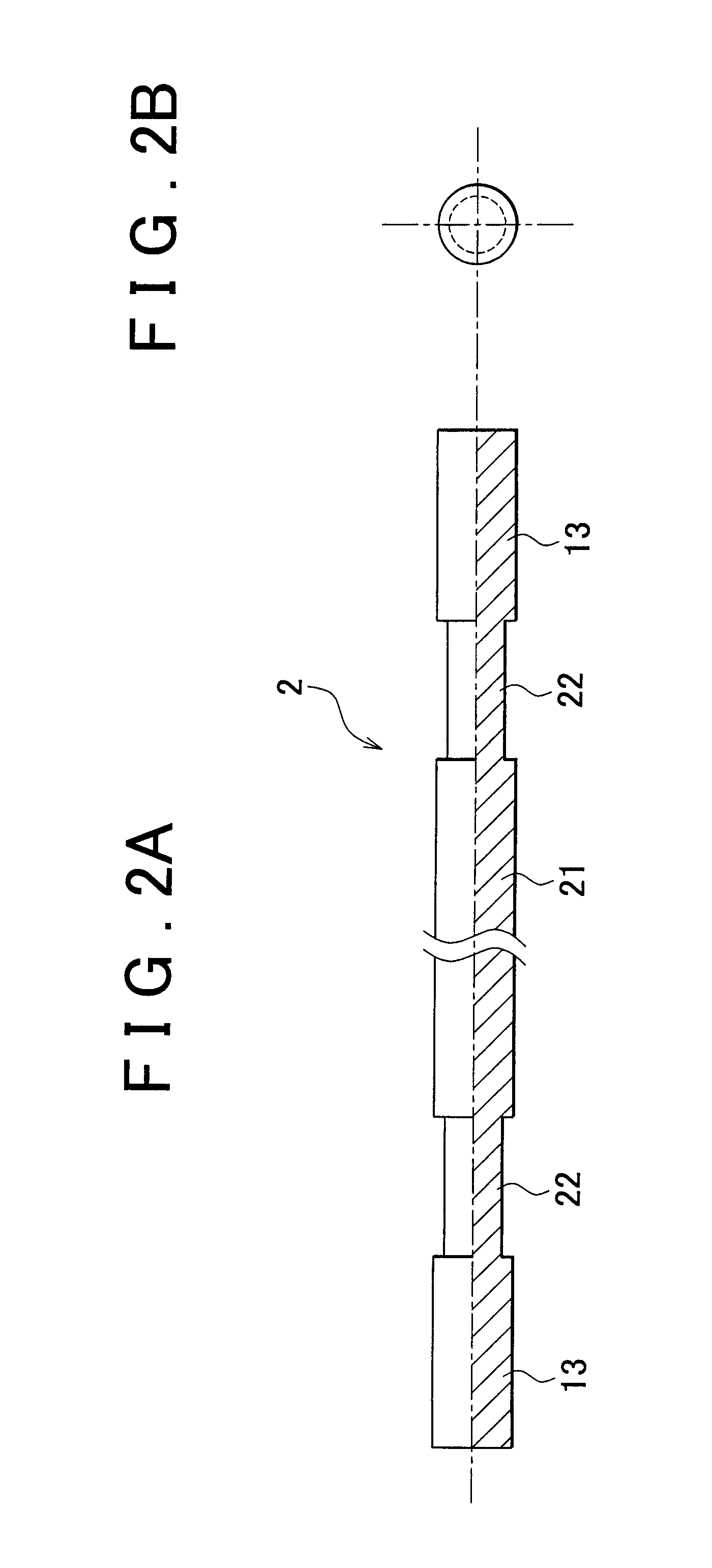
[0028]The resin laminating step is described first. FIG. 1 is a perspective view showing an application roller 1 according to the embodiment. FIG. 2A is a front view showing a roller body 2 (a lower half of which is shown in section), while FIG. 2B is a side view thereof. FIG. 3A is a front view showing the roller body 2 (the lower half of which is shown in section) having a resin layer 31 overlaid on outer periphery of a large diameter portion 21 and outer periphery of each of small diameter portions 22 thereof so that the resin layer has a cylind...


PUM

PropertyMeasurementUnit
Diameteraaaaaaaaaa

Abstract

A manufacturing method of an application roller that applies a coating solution onto a surface of a substrate, wherein the application roller includes a roller body that includes a large diameter portion and small diameter portions coaxially extended from both ends of the large diameter portion, the manufacturing method includes: overlaying a resin layer on at least an outer periphery of each of the small diameter portions; forming a masking portion on the outer periphery of each of the small diameter portions by processing an outer periphery of the resin layer; and forming an application groove portion on an outer periphery of the large diameter portion.

Description

INCORPORATION BY REFERENCE[0001]The disclosure of Japanese Patent Application No. 2011-135327 filed on Jun. 17, 2011 including the specification, drawings and abstract is incorporated herein by reference in its entirety.BACKGROUND OF THE INVENTION[0002]1. Field of the Invention[0003]The present invention relates to a manufacturing method of an application roller that applies a coating solution onto a surface of a substrate and also relates to an application roller.[0004]2. Description of Related Art[0005]Electrodes (positive electrode and negative electrode) of a lithium ion secondary battery are each prepared by forming a thin film on the surface of the substrate such as aluminum foil or copper foil as a current collector. The thin film is formed by applying a paste including an active material and a binder resin onto the surface of the substrate and by drying the paste. Increasing drying rate of the paste is effective in reducing costs for equipment for performing such an applicat...

Claims


Application Information

Patent Timeline
IPC IPC(8): B32B37/02B32B38/04B05C1/00H01M4/04H01M4/139
CPCH01M4/0404H01M4/139Y10T29/49563Y10T29/49982Y02E60/122Y02E60/10Y02P70/50
Inventor YAMAZAKI, NOBUYUKI
Owner TOYOTA JIDOSHA KK
Learn More