Automatic sunlight tracking device

a tracking device and automatic technology, applied in the direction of heat collector mounting/support, lighting and heating equipment, instruments, etc., can solve the problems of high price of photovoltaic cells, low utilization rate, and high generation cost in solar energy application, etc., to achieve easy production, simple structure, and reasonable and firm structure

Inactive Publication Date: 2012-12-20
LIU JIANZHONG
View PDF1 Cites 25 Cited by
  • Summary
  • Abstract
  • Description
  • Claims
  • Application Information

AI Technical Summary

Benefits of technology

[0024](1) The automatic sunlight tracking device according to the present invention has a simplified, reasonable and firm structure, and good mechanical performance. The device can be configured by multiple flexible combinations. Therefore, the device can be easily produced on mass production basis.
[0025](2) A driving power required by the device is considerably decreased due to reasonable and simplified structure of the invention. Operation energy consumption of the device itself is greatly reduced by means of an operation timing control program and self-locking of the worm wheel and worm.
[0026](3) The control program of the device is simplified by cooperation of the pitching angle tracking member and the swing angle tracking member so that accurate tracking can be achieved by an open-loop control system. The cost of the control system is reduced while probability of failure of the device is decreased, and installation and everyday maintenance of the device is facilitated.
[0027](4) The device is widely applicable. Tracking of sunlight with either large or small panels can produce considerable economic benefit.
[0028](5) The device solves the problem that the efficiency of the solar energy device varies as a point where the direct sunlight occurs moves between tropic of Capricorn and the tropic of Cancer. Therefore, the device can be widely used.

Problems solved by technology

However, nowadays the rate of utilization is generally low and generation cost is generally expensive in application of the solar energy especially in a field of photovoltaic generation.
Firstly, since existing photovoltaic cell for photovoltaic generation technique mainly employs semiconductor material such as monocrystalline silicon and polycrystalline silicon, the price of the photovoltaic cell is expensive.
Secondly, currently monocrystalline silicon panel of high-quality has only a photovoltaic conversion efficiency of up to about 17% and only a maximal lift time of twenty to thirty years so that cost of solar generation is enlarged and difficulty in marketing of solar generation is increased.
Therefore, that utilization efficiency of the sunlight is relatively low.
However, most of the existing sunlight tracking techniques result in a high cost even a cost exceeding 30% of total investment in a generation device due to reasons such as complex structure.
Furthermore, the tracking itself necessitates electrical energy consumption.
A generation system using the tracking technique occupies more land area than that using the fixed solar panel, needs additional technical staff for maintenance of equipment, and has more operation risk than that using the fixed solar panel.
In addition, in order to decrease tracking cost, currently, tracking devices made by manufacturers become increasingly bulky.
This in turn results in a series of problems such as greater wind resistance, increased difficulty in installation and maintenance, and improved requirements for road and foundation.
As a result, attraction of effect generated by the tracking technique is greatly decreased and commercialization of the sunlight tracking technique is hindered.

Method used


Image

  • Automatic sunlight tracking device
  • Automatic sunlight tracking device
  • Automatic sunlight tracking device

Examples


embodiment 1

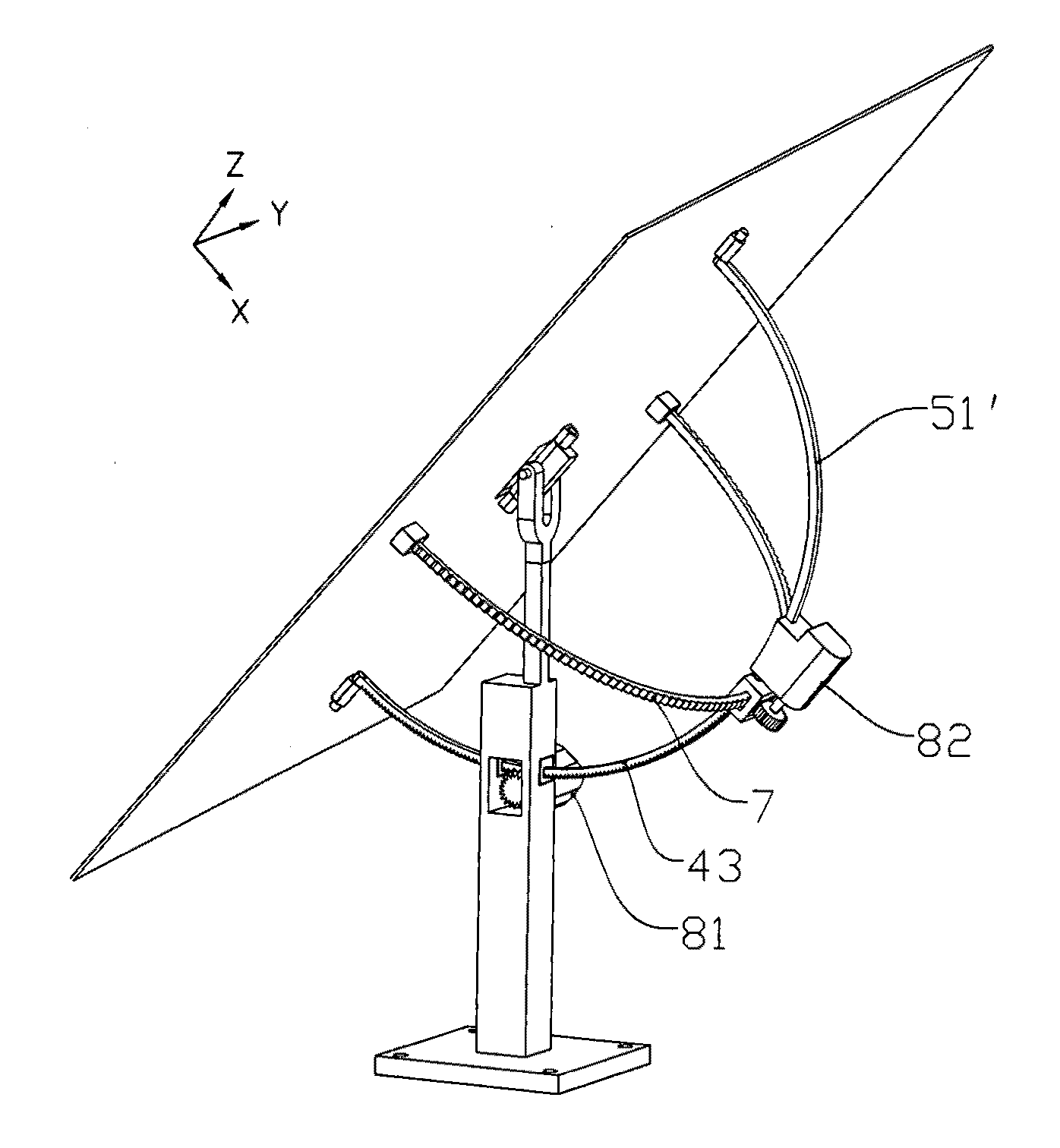
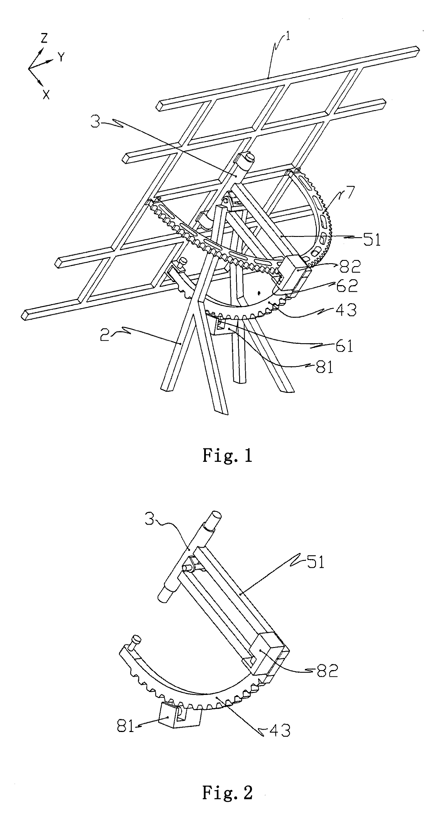
[0065]As illustrated in FIGS. 1-4, for purpose of clarity description, firstly, a Y direction is defined as a direction which is parallel to a plane in which the solar panel holder 1 is located and which is directed along a movement locus of the sun during one day, a Z direction is defined as a direction which is parallel to the plane in which the solar panel holder 1 is located and which is directed along a movement locus of the sun during one year, and then an X direction is defined as a direction which is perpendicular to a YZ plane and directed towards a back of the solar panel holder 1.

[0066]As shown in FIG. 4, the solar panel holder 1 can be a welded frame structure (or an aluminum section composite frame structure) for fixing a solar panel 11. Depending upon different latitude of regions where the solar panel is used, the solar panel 11 may be mounted parallel or at an inclination angle to the solar panel holder 1.

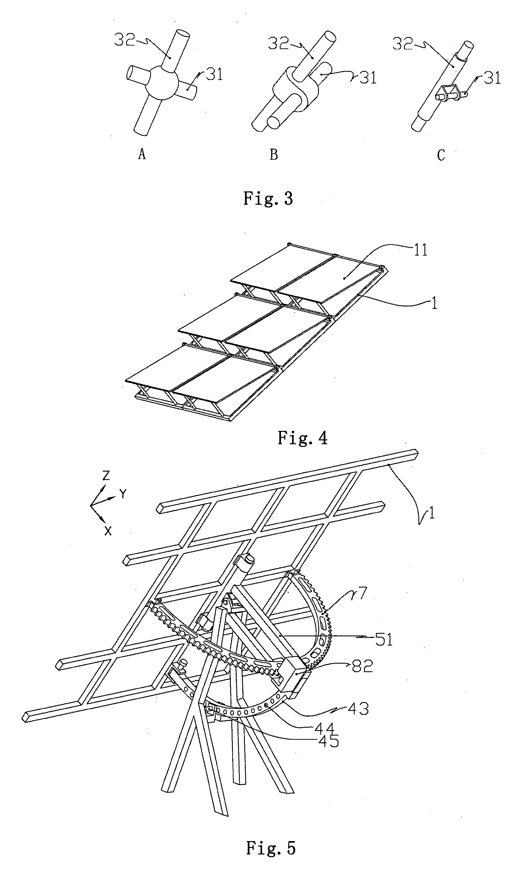
[0067]The mounting 2 is a lambdoid steel structure formed by w...

embodiment 2

[0082]As shown in FIG. 5, the second embodiment is different from the first embodiment in that the rigid arc body 43 has a hole-shaped positioning structure. The positioning structure is an array of positioning holes 44 uniformly distributed on the rigid arc body so that angle adjustment and fixation can be achieved. The mounting 2 is provided with a fixation hole corresponding to the positioning holes 44 at a position adjacent to the rigid arc body 43. A positioning pin 45 (such as a cylindrical pin) can be inserted between the positioning hole 44 and the fixation hole to lock the rigid arc body 43 and the mounting 2 together. Therefore, a simple manual first drive device is formed so as to manually adjust the pitching angle.

[0083]The swing angle tracking member of the second embodiment is substantially the same as that of the first embodiment.

[0084]The embodiment can automatically track the sunlight with a single shaft, but the pitching angle needs to be manually adjusted at inter...

embodiment 3

[0086]As showed in FIGS. 6 and 7, the third embodiment is different from the first embodiment in that the first transmission part is a transmission rope of a rope-like body and includes a third transmission rope 41 and a fourth transmission rope 42.

[0087]The first drive device comprises an electric motor and a worm speed reducer. A pulley 9 cooperating with the transmission ropes is mounted on an output shaft of the worm speed reducer. The pulley 9 has a cylindrical shape with a small diameter at a middle portion and a large diameter at both ends. The diameters are gradually changed from the middle portion to both sides. Third and fourth helical guide grooves 91 and 92 symmetrical about an intermediate cross section of the pulley are disposed on a cylindrical surface of the pulley. Helical directions of the two helical guide grooves are opposite to each other. Depths of the two helical guide grooves are designed according to requirements for winding of the transmission ropes. The th...


PUM


Abstract

Disclosed is an automatic sunlight tracking device comprising a solar panel holder (1), a mounting (2), a pitching angle tracking member, and a swing angle tracking member. The solar panel holder (1) is coupled with the mounting (2) through a three-dimensional assembly (3), and the pitching tracking member comprises a first transmission part and a first drive device (81) cooperating with the first transmission part. The swing tracking member comprises a second transmission part and a second drive device (82) cooperating with the second transmission part. The three-dimensional assembly (3) includes two rotation supporting shafts arranged in a cross shape. The automatic sunlight tracking device has a high operation accuracy, a reasonable structure, low operation energy consumption. It is easy to be controlled, and installation and maintenance is facilitated.

Description

BACKGROUND OF THE INVENTION[0001]1. Field of the Invention[0002]The present invention relates to a solar energy utilizing device, and particularly to an automatic sunlight tracking device having a function of tracking sunlight with two shafts.[0003]2. Description of the Related Art[0004]Since fossil energy is being exhausted and problems such as environmental pollution and greenhouse effect are generated during production and use of the fossil energy become more and more serious, countries have attached increasing importance to development and utilization of new energy source. The solar energy is new energy that is effective, clean, widely distributed, and can be nearly limitedly utilized, this attracts people to gradually and significantly increase investment in development of the solar energy. However, nowadays the rate of utilization is generally low and generation cost is generally expensive in application of the solar energy especially in a field of photovoltaic generation. Thi...

Claims


Application Information

Patent Timeline
Patent Type & Authority Applications(United States)
IPC IPC(8): H01L31/052F24S50/20
CPCG05D3/105F24J2/5424F24J2002/5441F24J2002/5458H01L31/054F24J2002/5486Y02E10/47H01L31/0522F24J2/5264F24J2002/5462F24S25/70H02S20/30F24S30/455F24S2030/115F24S2030/133F24S2030/134F24S2030/16Y02E10/52H02S20/32
Inventor LIU, JIANZHONG
Owner LIU JIANZHONG
Why Eureka
Try Eureka