Micro-nozzle thruster

a micro-nozzle and thruster technology, applied in the field of micro-and nano-satellites, can solve the problems of limited propellant temperature, limited specific impulse practical limitation, and general limitation of micro-propulsion payload units, and achieve high specific impulses, reduce the amount of propellant, and high v requirements

Inactive Publication Date: 2012-12-20
MICROSPACE RAPID PTE
View PDF15 Cites 6 Cited by
  • Summary
  • Abstract
  • Description
  • Claims
  • Application Information

AI Technical Summary

Benefits of technology

[0035]In contrast to chemical propulsion, there is no material temperature limitation to the speed of ions leaving an electric propulsion rocket and therefore very high specific impulses can be obtained. This makes electric propulsion interesting for very high ΔV requirements thanks to the reduced amount of propellant that needs to be stored.
[0036]It is the low thrust and high specific impulse that makes the electrical propulsion interesting for long duration non impulsive manoeuvres.
[0037]In one embodiment of the invention, the thruster may include a resistor to pre-heat the gas reaching the nozzle or to vaporize a liquid before it reaches the nozzle (resistojet preheating). Further, a resistor may be used to pre-heat the cathode thereby enhancing the release of electrons by thermionic emission (cathode emitter).
[0039]In a further embodiment, a magnetic field inside the nozzle may be produced by permanent magnets or coils placed outside the nozzle, to create a magnetic confinement of the plasma in the central portion of the nozzle thereby reducing wall heat losses. In the case of the nozzle having a prismatic structure, the nozzle may be inserted in the gap of a magnetic circuit. Such an arrangement may have minimal losses of magnetic flux (magneto hydrodynamic confinement).
[0042]In a further embodiment, a mix of gases or gases and liquids or gases and solid particles may be injected to facilitate ionization, to increase the momentum of the ejected material or to produce a thermal or deposition coating effect to materials placed in the ejected stream (plasma torch).
[0045]The more intimate such transfer can be achieved inside the gas, the less energy will be lost to the nozzle walls. One of the best ways to provide such energy is by creating a current through the gas in form of a spark, a discharge arc or plasma. The core of the arc can be sufficiently far from the nozzle walls to minimize the thermal losses and maximize the transfer to the gas reaching temperatures between 5000K and 10000K or more without damage to the nozzle walls.

Problems solved by technology

Until now, launches are always arranged in piggyback fashion whereby the largest cost of the launch is paid by a very big satellite and the nano or microsatellite are taken in an orbit and with a schedule which are not necessarily the optimal for their needs and interests.
A challenge for achieving a small thrust is to do it efficiently in order to have the best use of the limited amount of propellant available on board.
The temperature achievable by the propellant is ultimately limited by the combustion chamber and expansion nozzles materials giving a practical limitation to the specific impulse of chemical propulsion systems.
While many laboratories worldwide are studying and prototyping systems based on various principles, there are very few examples of micro and nano-satellites carrying a micro-propulsion unit.
Furthermore, such units are generally limited to a micro-propulsion payload and do not perform a primary mission requirement.

Method used


Image

  • Micro-nozzle thruster
  • Micro-nozzle thruster
  • Micro-nozzle thruster

Examples


Embodiment Construction

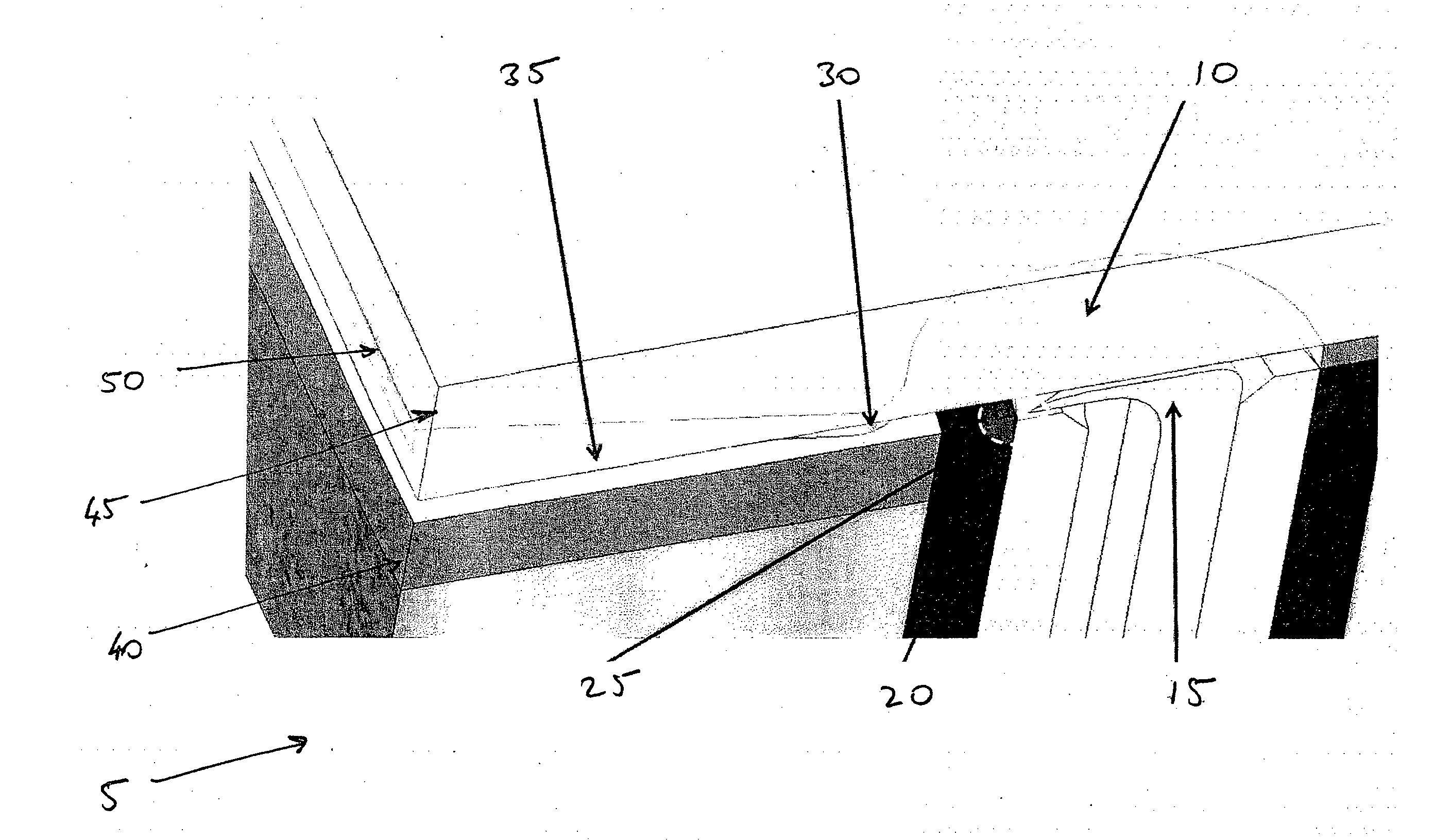
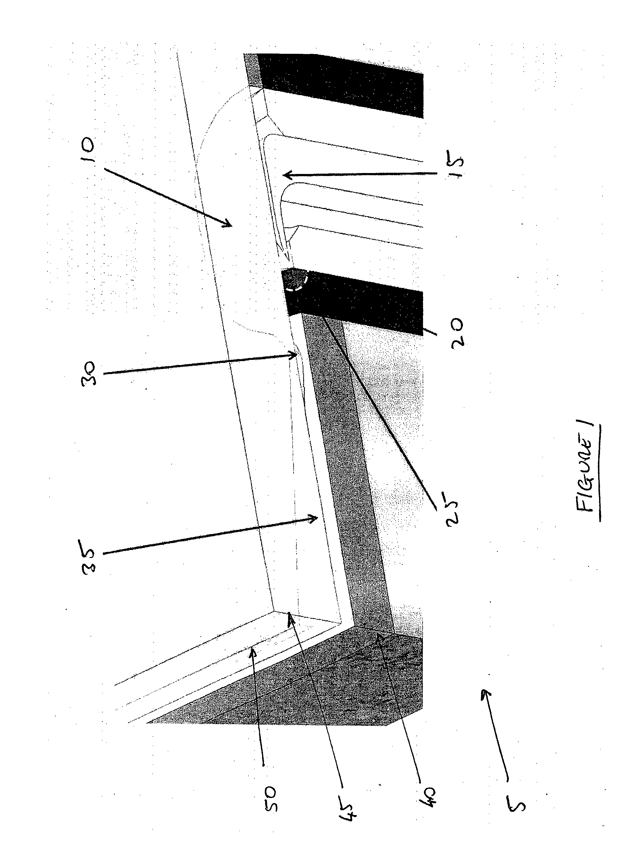
[0061]In describing the invention, an embodiment is shown in FIG. 1. The invention is directed to miniaturized arcjets 5 which uses the following basic elements:[0062]1. a generally prismatic micro-nozzle 35 which may be micro-machined using techniques such as micro-lithography, Deep Reactive Ion Etching, Anodic Bonding and Dicing using substrates 40, 45, such as silicon and glass with inlet 25 in the central area of the substrate and outlet, or exit, on one of the sides.[0063]2. A gas supply channel 10 made of substrates of insulating material such as ceramic or glass reaching the nozzle inlet perpendicularly to the substrate in correspondence of a through hole micro-machined in one or both the substrate(s).[0064]3. An anode element 20 placed externally to the gas supply channel, but internally to the nozzle inlet 25, possibly in the form of an electrically conducting ring and oriented between the channel and the nozzle throat 30;[0065]4. A cathode element 15 placed internally to t...


PUM


Abstract

A micro-nozzle thruster comprising a micro-nozzle having an inlet at a first end perpendicularly aligned gas supply channel at a first end, and a thruster outlet at a second opposed end; said inlet in fluid communication with a gas supply channel, said gas supply channel perpendicularly aligned with a longitudinal axis of the micro-nozzle; a cathode within the gas supply channel and an anode external to the gas supply channel and proximate to the inlet, so as to create a plasma flow from said gas.

Description

FIELD OF THE INVENTION [0001]The invention relates to micro- and nano-satellites, and in particular, thrusters for the maneuvering of said satellites.BACKGROUND [0002]Satellites and spacecrafts miniaturization is a recognized trend covering the whole range of space missions from simple university missions designed by students to sophisticated military satellites and interplanetary probes. The rationale for miniaturization comes from the drastic launch and manufacturing cost reductions in combination with the growing offer and availability of new miniaturized parts, subsystems and satellite buses.[0003]Besides such scientific missions, the first obvious tasks for micro and nano-satellites are Earth observation for environmental, military and geological uses, while telecommunications will follow as soon as the other technological building blocks will be available. Last but not least, missions related to entertainment and space tourism will become common as soon as rocket plane launche...

Claims


Application Information

Patent Timeline
Patent Type & Authority Applications(United States)
IPC IPC(8): F02K7/00
CPCF03H1/0037B64G1/405B64G1/40H05H1/54F03H1/0093F03H1/0081F03H1/0056F03H1/0087F03H1/0043B81B2201/038B64G1/415F03H1/00H05H1/50
Inventor MANZONI, GIULIO
Owner MICROSPACE RAPID PTE
Why Eureka
Try Eureka