Radioactive ray generating apparatus and radioactive ray imaging system

a radioactive ray imaging technology, applied in the direction of instruments, heat measurement, machines/engines, etc., can solve the problems of difficult downsizing of the radioactive ray generating apparatus, achieve excellent heat resistance, reduce the heat load of the target, and effectively release the generated heat

Active Publication Date: 2012-12-20
CANON KK
View PDF16 Cites 22 Cited by
  • Summary
  • Abstract
  • Description
  • Claims
  • Application Information

AI Technical Summary

Benefits of technology

[0015]According to the first invention, heat generated when an electron beam collides against the target can be quickly released to the first shielding member. The heat can be subsequently released to the second shielding member. Therefore, the generated heat can be effectively released, and the heat load of the target can be reduced. Thus, the radioactive ray generating apparatus which is excellent in heat resistance and does not damage the target can be realized. Further, the radioactive ray generating apparatus can be downsized if a transmission-type target is employed for the radioactive ray generating apparatus.
[0016]According to the second invention, the efficiency in generation of radioactive rays can be improved because reflection electrons are appropriately guided toward the target again after the reflection...

Problems solved by technology

However, if a radioactive ray generating apparatus is configured to include a radioactive ray tu...

Method used


Image

  • Radioactive ray generating apparatus and radioactive ray imaging system
  • Radioactive ray generating apparatus and radioactive ray imaging system
  • Radioactive ray generating apparatus and radioactive ray imaging system

Examples


first exemplary embodiment

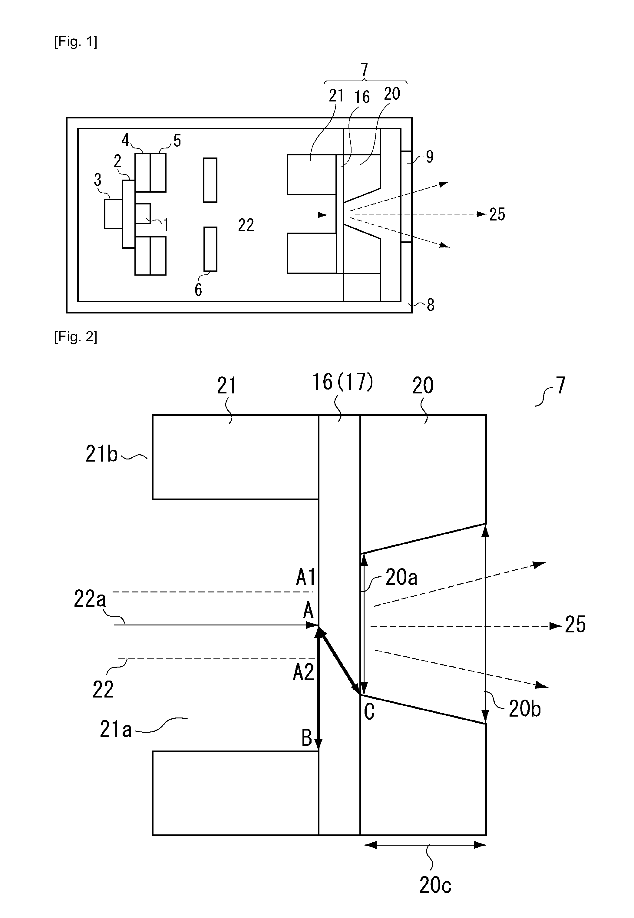
[0033]An example configuration of the radioactive ray generating apparatus according to a first exemplary embodiment of the first invention is described below. FIG. 1 is a cross-sectional view illustrating an example configuration of the radioactive ray generating apparatus according to the present exemplary embodiment.

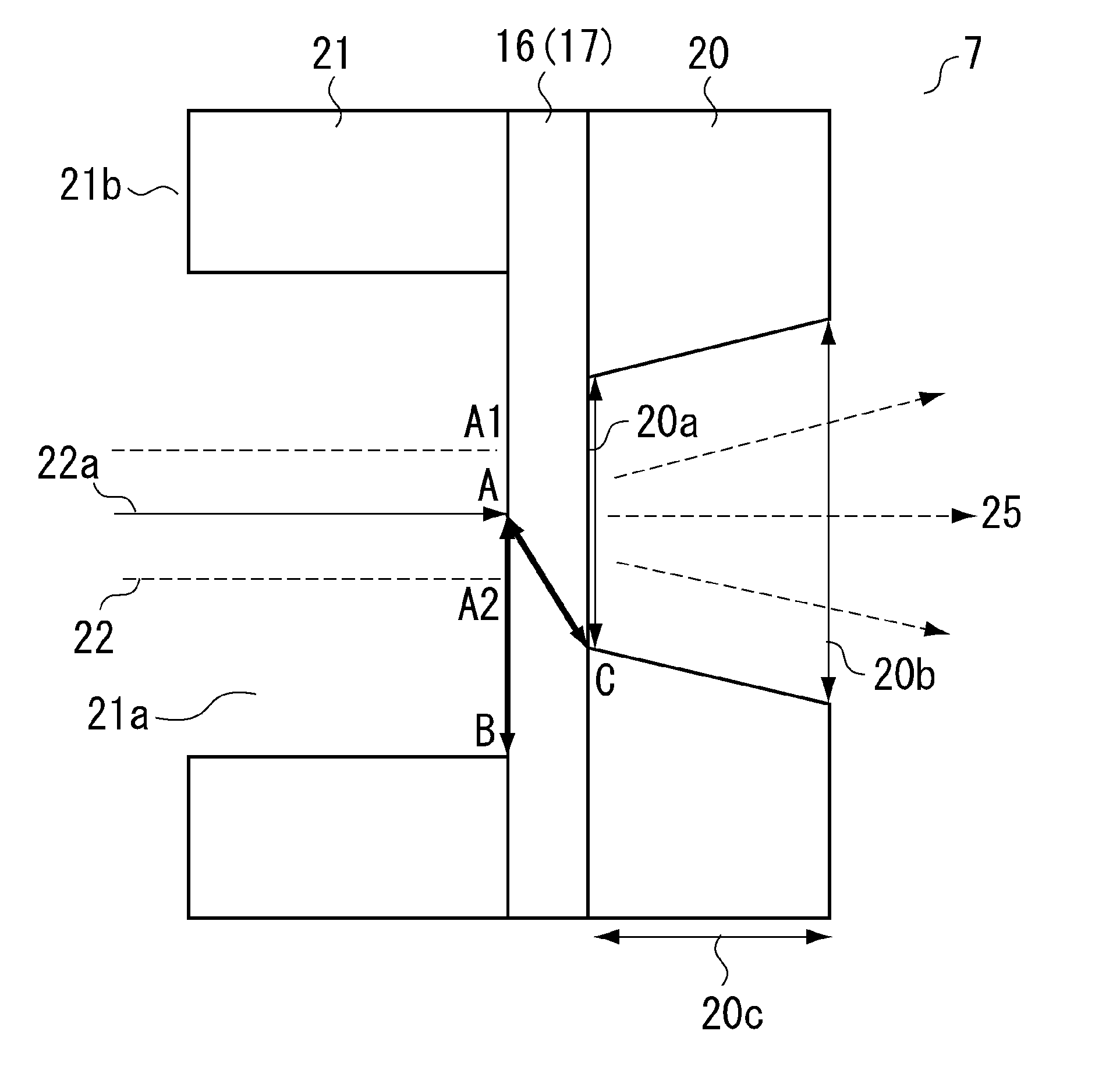
[0034]The radioactive ray generating apparatus according to the present exemplary embodiment includes an electron emission source 1, a target 16, and a shielding member. The target 16 is disposed to face the electron emission source 1 and generates radioactive rays by being irradiated with electrons emitted from the electron emission source 1. The shielding member can shield radioactive rays emitted from the target 16. The target 16 and the shielding member including a first shielding member 20 and a second shielding member 21 cooperatively constitute an anode 7. In the example radioactive ray generating apparatus according to the present exemplary embodiment, the ele...

second exemplary embodiment

[0061]A configuration of a radioactive ray generating apparatus according to a second exemplary embodiment of the first invention is described below. FIG. 5 is a cross-sectional view illustrating an example configuration of the radioactive ray generating apparatus according to the present exemplary embodiment.

[0062]The radioactive ray generating apparatus according to the present exemplary embodiment is similar to the radioactive ray generating apparatus described in the first exemplary embodiment of the first invention, except that the target 16 functions as a vacuum sealing member and a radiation extraction window and at least a part of the first shielding member 20 is kept in contact with a cooling medium (not illustrated), as illustrated in FIG. 5. Although the configuration illustrated in FIG. 5 does not include a heater, a grid electrode, a grid electrode support member, and a focusing electrode, the radioactive ray generating apparatus may include the heater 3, the grid elect...

third exemplary embodiment

[0065]An example of the anode 7 according to a third exemplary embodiment of the first invention is described below in more detail. FIG. 6 is a cross-sectional view illustrating an example configuration of the anode 7 according to the third exemplary embodiment.

[0066]A radioactive ray generating apparatus according to the present exemplary embodiment is characterized in that the target 16 includes a transmissive substrate 18 and a target film 17 as illustrated in FIG. 6. The transmissive substrate 18 is a member through which radioactive rays can be transmitted. The target film 17 is disposed on the electron emission source side of the transmissive substrate 18. Any other type of target 16 can be used if it includes members that are functionally operable as the transmissive substrate 18 that can transmit radioactive rays and the target film 17 provided on the electron emission source side of the transmissive substrate 18. The rest of the members illustrated in FIG. 6 are similar to ...


PUM


Abstract

A radioactive ray generating apparatus includes a second shielding member, a target, and a first shielding member, which are sequentially disposed from an electron emission source side. A shortest distance from a maximum radiation intensity portion of the target to the first shielding member is shorter than a shortest distance from the maximum radiation intensity portion of the target to the second shielding member.

Description

TECHNICAL FIELD[0001]The present invention relates to a radioactive ray generating apparatus that can irradiate a target with electrons to generate radioactive rays and can be used in an X-ray image capturing operation. Further, the present invention relates to a radioactive ray imaging system that includes the radioactive ray generating apparatus.BACKGROUND ART[0002]A radioactive ray generating apparatus, which is generally usable as a radiation source, includes an electron emission source that can emit electrons and a radioactive ray generation mechanism that causes generated electrons to collide against a target, which is made of a material having a larger atomic number (e.g., tungsten), to generate radioactive rays. The radioactive ray generated from the target propagates in all directions. Therefore, a shielding member is provided to shield unnecessary radioactive rays that are not available for an image capturing operation. However, if a radioactive ray generating apparatus is...

Claims


Application Information

Patent Timeline
IPC IPC(8): H01J43/00
CPCH01J35/08H01J35/16H01J35/18H01J2235/068H01J2235/186H01J2235/163H01J2235/166H01J2235/168H01J2235/087H01J35/116H01J35/186
Inventor MIYAZAKI, KAZUYAOGURA, TAKAOUEDA, KAZUYUKISATO, YASUENOMURA, ICHIROAOKI, SHUJITAMURA, MIKI
Owner CANON KK
Why Eureka
Try Eureka