Apparatus for Stabilizing Mechanical, Thermal, and Optical Properties and for Reducing the Fluorescence of Biological Samples for Optical Evaluation

a biological sample and optical evaluation technology, applied in the field of optical evaluation, can solve the problems of difficult to obtain a calibration for the analyte concentration from multiple sites, interfere with the measurement, and local burn to the skin of the subject, and achieve the effect of substantially reducing the unwanted fluorescence of targeted fluorophores

Active Publication Date: 2012-12-20
DIABESEN TECH BEIJING CO LTD
View PDF1 Cites 10 Cited by
  • Summary
  • Abstract
  • Description
  • Claims
  • Application Information

AI Technical Summary

Benefits of technology

[0015]e. Unwanted fluorescence from targeted fluorophores can be substantially reduced.

Problems solved by technology

If the spectra of the chemicals which vary from site to site have some overlap with the spectrum of the analyte of interest, it is often difficult to obtain a calibration for the analyte concentration from multiple sites.
In cases where lasers which deliver substantial power levels must be used to illuminate the sample, in order to obtain an adequate signal, the temperature increase caused by the laser radiation can interfere with the measurement.
At sufficiently high powers the elevation of temperature caused by the laser can also damage or destroy proteins by denaturation, and cause a local burn to the skin of the subject.
In such cases however, evaporation of volatile compounds such as water is impeded by the presence of the window.
The changing scattering and reflection characteristics may make it impossible to observe other changes that may be occurring on the same time scale.
For example, if the concentration of some analyte in the skin is changing, the signal from spectroscopy for that analyte would be expected also to change, however, the changing scattering properties will also affect the size of the signal which is observed, and it can be exceptionally difficult to distinguish the two effects.
If the pressure is not fixed in time, the effects of changes in pressure can also be difficult to distinguish from changes in signal size associated with fluctuations in what is desired to be measured.
Finally, it is also the case that fluorescence from fluorophores present in the sample (autofluorescence), can interfere with certain forms of spectroscopic evaluation.
If it is desired to obtain the Raman spectrum of an analyte of interest in human skin, the fluorescence induced by the laser, which is used to irradiate the sample, is usually the principle source of random noise in the measurement.
In other cases, the fluorescence of one analyte is of interest, but the fluorescence of a second chemical which is also present in the sample is not of interest and is a source of unwanted interference.
If this process is interrupted by moving to a new spot on the sample, then the decay will start over again, thus complicating the analysis.

Method used


Image

  • Apparatus for Stabilizing Mechanical, Thermal, and Optical Properties and for Reducing the Fluorescence of Biological Samples for Optical Evaluation
  • Apparatus for Stabilizing Mechanical, Thermal, and Optical Properties and for Reducing the Fluorescence of Biological Samples for Optical Evaluation
  • Apparatus for Stabilizing Mechanical, Thermal, and Optical Properties and for Reducing the Fluorescence of Biological Samples for Optical Evaluation

Examples


Embodiment Construction

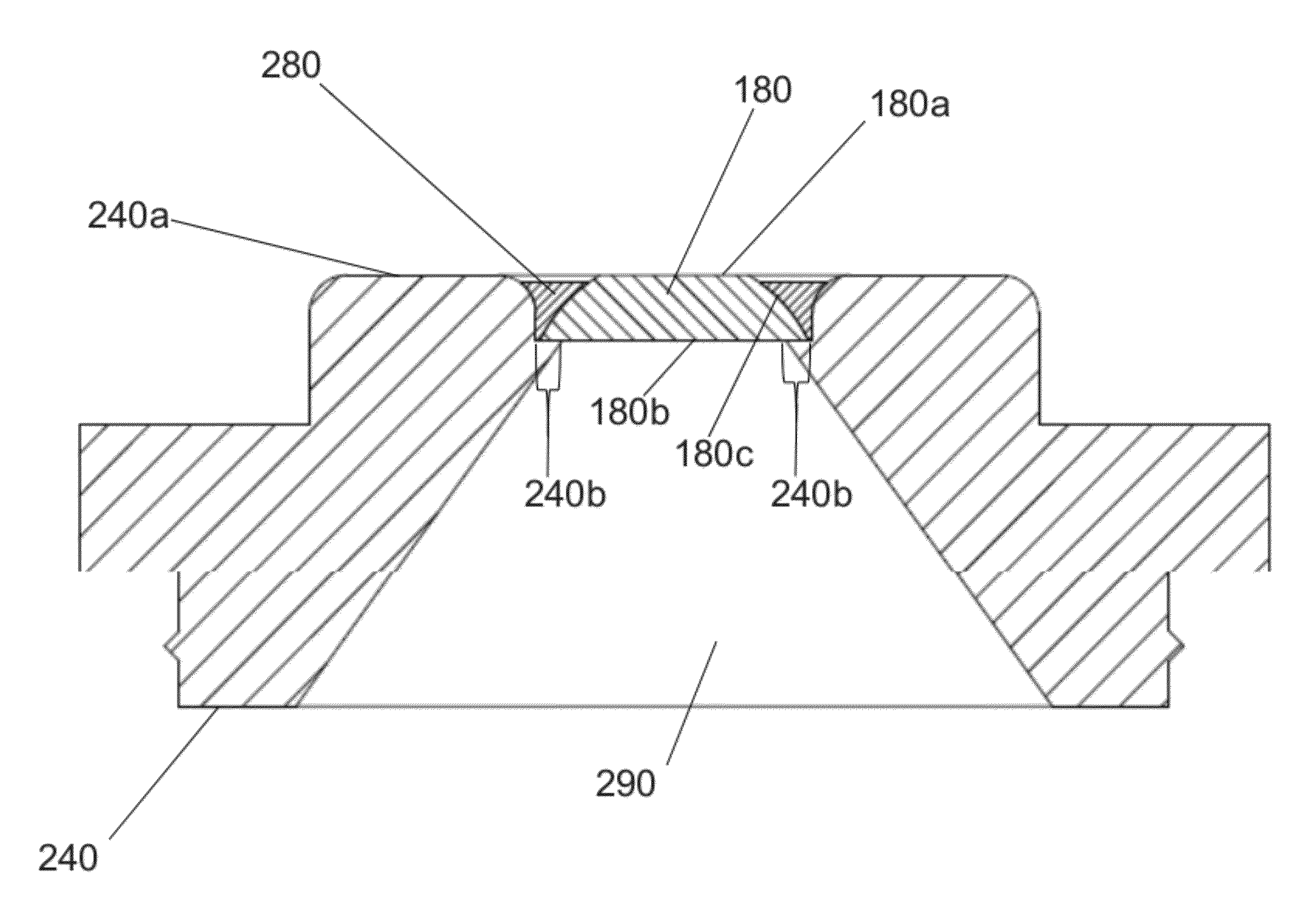
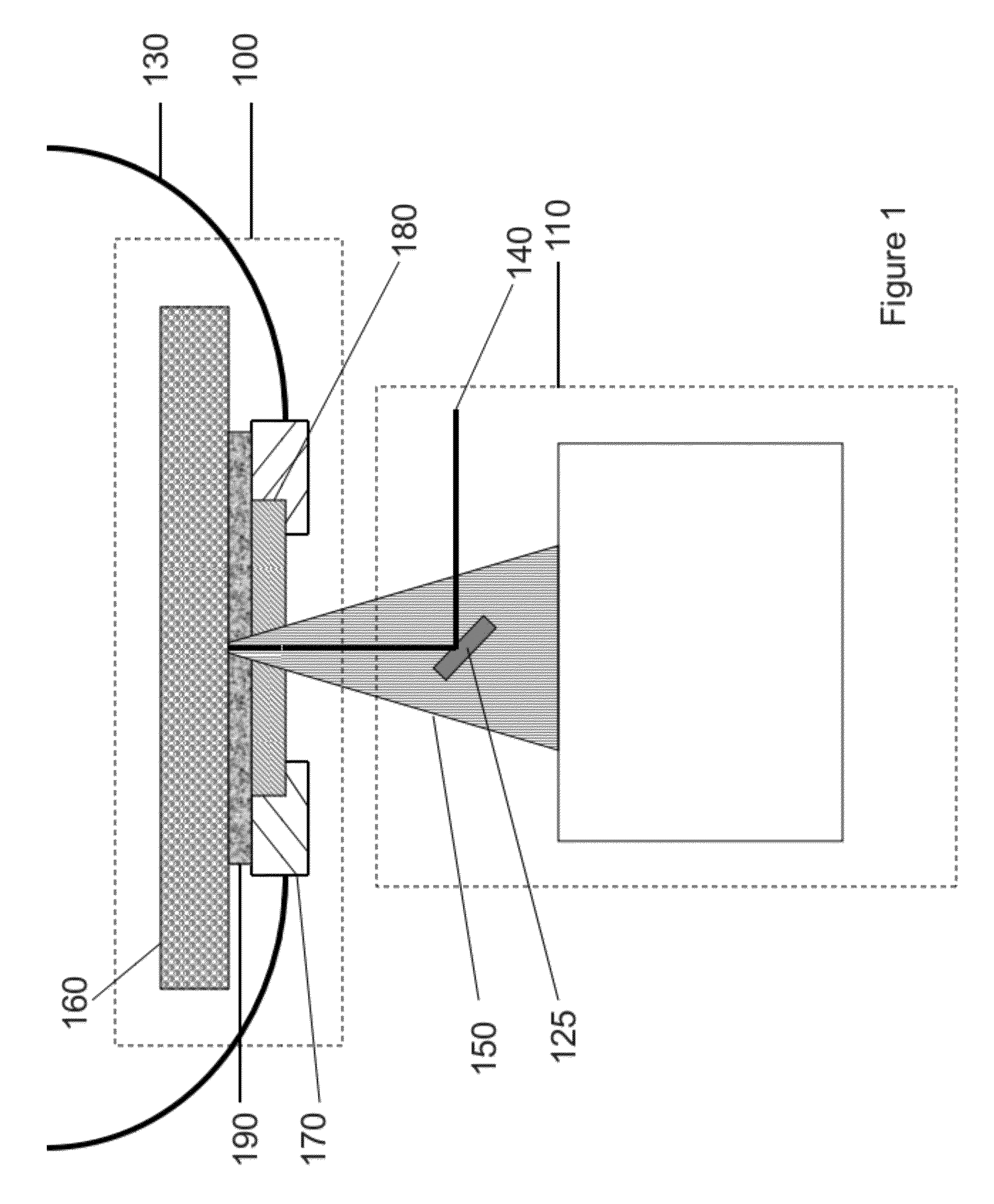
[0033]FIG. 1 is a cross-section diagram of the apparatus, in accordance with an embodiment. The apparatus is comprised of the sample apparatus 100, which includes a strap 130 disposed on either side to secure the sample apparatus 100 to the test subject or sample 160, and the spectroscopic and / or imaging system 110. The spectroscopic and / or imaging system 110 comprises the light excitation beam 140 which arises from a source within the spectroscopic and / or imaging system 110, a mirror 125 that is one means of introducing the beam 140 to the sample 160, and appropriate collection optics (not shown) to capture and guide the scattered radiation 150 from the sample 160 that passes from the sample apparatus 100 to the spectroscopic and / or imaging system 110. The excitation beam 140 passes between the spectroscopic and / or imaging system 110 and the sample apparatus 100. In FIG. 1, the sample apparatus 100 is comprised of an optical window 180 and frame 170 which retains the optical window...


PUM

PropertyMeasurementUnit
wavelengthaaaaaaaaaa
detected wavelengthaaaaaaaaaa
wavelengthsaaaaaaaaaa

Abstract

An apparatus is presented for stabilizing an optical, thermal, and mechanical interface between a spectroscopic and/or imaging system and a biological sample. The apparatus includes a window retainer having a retainer surface and a well. The retainer surface surrounds the well. Further, the retainer surface is substantially planar. An optical window is located in the well. The optical window comprises a first and second surface. The second surface is in contact with the window retainer. The first surface is substantially flush with the retainer surface. The apparatus further includes an attachment mechanism coupling the window retainer to the biological sample such that a fluid, gel, adhesive or elastomer interposed between the optical window and the biological sample is trapped in the well.

Description

CROSS REFERENCE TO RELATED APPLICATIONS[0001]This application is related to U.S. patent application Ser. No. 12 / 026,478 , filed on Feb. 5, 2008, the contents of which are incorporated by reference herein in their entirety.BACKGROUND OF THE INVENTION[0002]1. The Field of the Invention[0003]This invention relates generally to stabilizing the position, temperature, and optical scattering characteristics of a biological sample undergoing optical evaluation.[0004]2. Background and Relevant Art[0005]Many forms of optical evaluation are being developed as noninvasive means of characterizing the chemistry and morphology of biological samples. In a number of applications it is desired to ascertain important properties of the tissue by spectroscopic analysis. For example, spectroscopy can be used to ascertain the concentration of an analyte of interest within the sample. In such cases, there may be variations in the chemical composition of the sample as a function of position (site to site va...

Claims


Application Information

Patent Timeline
Patent Type & Authority Applications(United States)
IPC IPC(8): G01N21/01
CPCG01N21/01
Inventor LIPSON, JANBERNHARDT, JEFFREY M.MCNAMARA, ROBERT P.HOFMEISTER, RUDOLF J.ICE, DONALD A.LIPSON, JANYCE
Owner DIABESEN TECH BEIJING CO LTD
Why Eureka
Try Eureka