Combustion appliance for raising the temperature of exhaust gas

Inactive Publication Date: 2012-12-20
HINO MOTORS LTD
View PDF5 Cites 36 Cited by
  • Summary
  • Abstract
  • Description
  • Claims
  • Application Information

AI Technical Summary

Benefits of technology

[0018]In the combustion appliance for raising the temperature of the exhaust gas according to the invention, various beneficial effects can be obtained as follows:
[0019](I) The combustion air introduced through the combustion air inflow holes into the periphery of the inner cylinder at the proximal end thereof reliably avoids shortage of oxygen in the ignition, and the swirling flow of the combustion air formed by the peripheral fins facilitates early mixing of the combustion air with the fuel mist, thereby stabilizing the ignition of the fuel mist. In addition, the swirling flows formed by the peripheral and end fins enhances the combustibility to substantially improve the flame-stabilizing performance. Thus, the exhaust gas can be raised in temperature while effectively preventing flame-out and imperfect combustion.
[0020](II) When a mixer divergent in a direction of fuel injection is arranged on the distal end of the stabilizer and a plurality of tapered-surface fins are formed on a tapered surface of the mixer radially inwardly of the mixer through cutting and bending-up such that exhaust gas is introduced from circumferentially to form a swirling flow inside the mixer, the flame blown out of the inner cylinder can stably spread without being fanned by the flow of the exhaust gas, and the flow of the exhaust gas is introduced through

Problems solved by technology

However, a captured amount of particulates will exceed a treated amount of particulates in operation areas with low exhaust temperature levels.
Continued operation with such low e

Method used


Image

  • Combustion appliance for raising the temperature of exhaust gas
  • Combustion appliance for raising the temperature of exhaust gas
  • Combustion appliance for raising the temperature of exhaust gas

Examples


Example

[0033]An embodiment of the invention will be described with reference to the drawings.

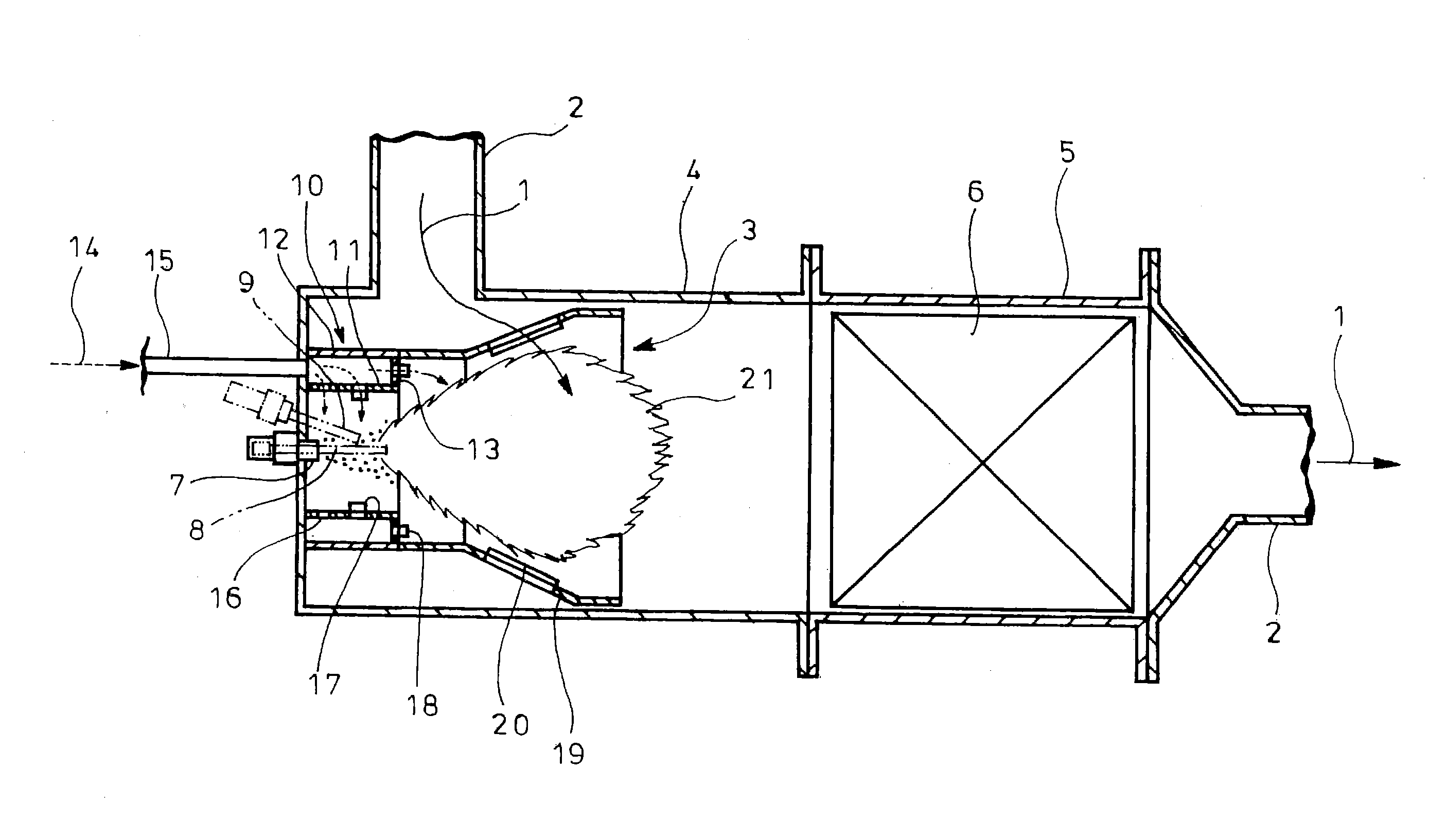
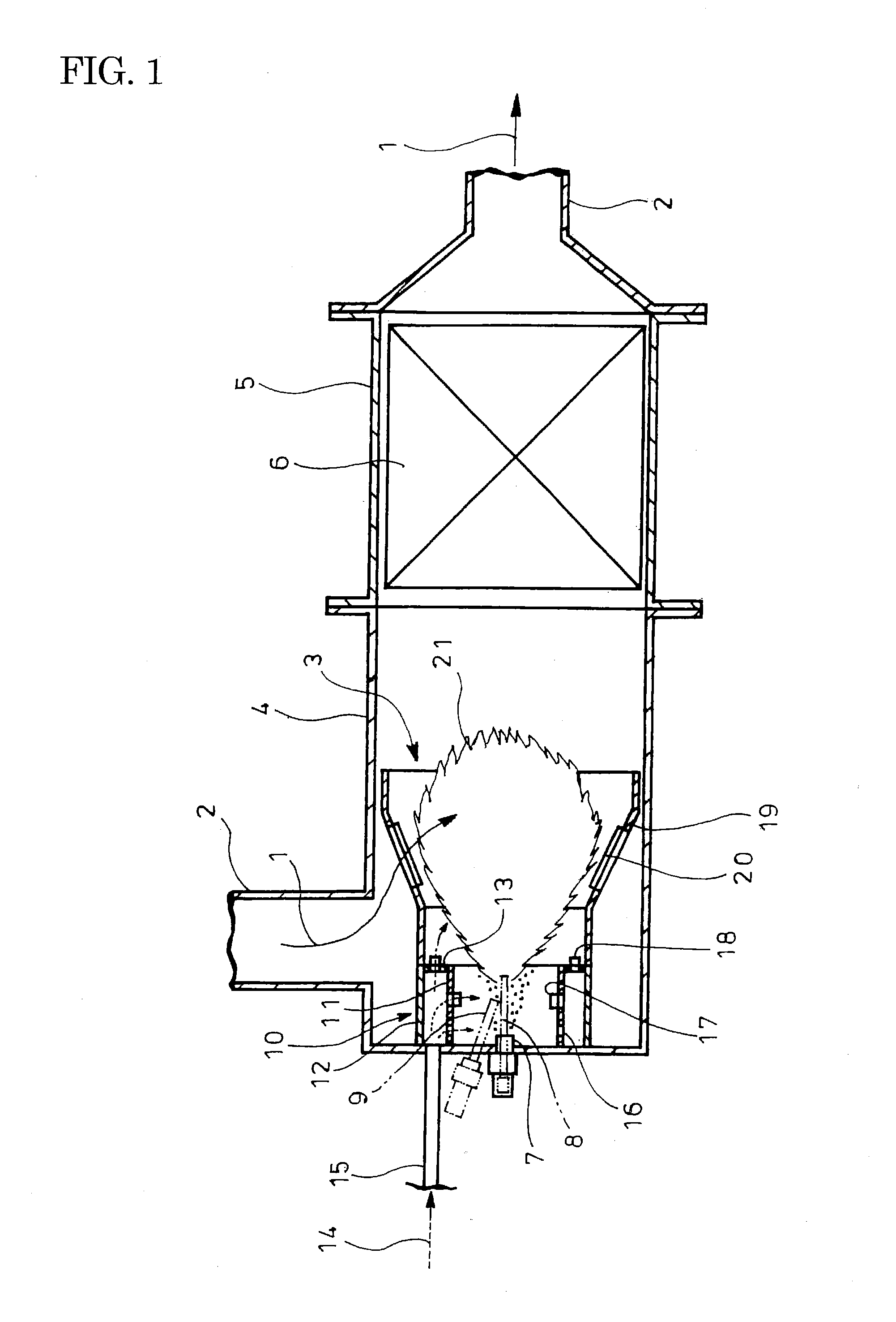
[0034]FIG. 1 shows the embodiment of the invention. In FIG. 1, reference numeral 2 denotes an exhaust pipe which guides exhaust gas 1 having passed through a turbine (not shown) of a turbocharger. The exhaust pipe 2 has an L-shaped bend in which arranged is a combustion appliance 3 for raising the temperature of the exhaust gas 1 by burner combustion.

[0035]The bend of the exhaust pipe 2 is provided by a casing 4 arranged substantially perpendicular to the exhaust pipe 2 extending from upstream. Encased in the casing 4 is the combustion appliance 3, and interposed between the casing 4 and the exhaust pipe 2 on a downstream side is a particulate filter 6 encased in a further casing 5.

[0036]On a side of the casing 4 opposite to the particulate filter 6, the combustion appliance 3 includes a fuel injection nozzle 7 which injects the fuel downstream in a direction of flow of the exhaust gas 1 and a pair...


PUM


Abstract

Injection nozzle 7 and electrode rods 8 and 9 (ignitor) are surrounded by double-cylinder flame stabilizer 10. Toroidal blocking plate 13 closes between inner and outer cylinders 11 and 12 of the stabilizer at its distal end whose proximal end is connected with line 15 for introducing combustion air 14 to between the cylinders. Inflow holes 16 are formed throughout the inner cylinder at its proximal end. Peripheral fins 17 are formed peripherally on the inner cylinder radially inwardly through cutting and bending-up at positions shifted from the inflow holes toward the distal end of the inner cylinder such that combustion air is introduced from circumferentially to form swirling flow inside the inner cylinder. End fins 18 are formed on the blocking plate in fuel injection direction through cutting and bending-up such that combustion air is discharged circumferentially to form swirling flow around flame 21.

Description

TECHNICAL FIELD[0001]The present invention relates to a combustion appliance for raising the temperature of exhaust gas.BACKGROUND ART[0002]Conventionally, a diesel engine has a particular filter incorporated in an exhaust pipe for flow of exhaust gas to capture particulate matters or particulates in the exhaust gas. An oxidation catalyst having active species such as Pt or Pd is integrally carried by this kind of particulate filter for self-burning of the captured particulates even at a minimally low exhaust temperature.[0003]However, a captured amount of particulates will exceed a treated amount of particulates in operation areas with low exhaust temperature levels. Continued operation with such low exhaust temperature levels may hinder sufficient regeneration of the particulate filter, resulting in excessive accumulation of the captured particulates in the particulate filter.[0004]Conventionally proposed in this connection is to arrange a combustion appliance for raising the temp...

Claims


Application Information

Patent Timeline
IPC IPC(8): F23D11/00
CPCF01N3/0256F23D2900/21003F23D2900/21006F23G7/065F01N2240/14F01N2240/20F01N2470/18F01N3/025
Inventor TSUMAGARI, ICHIROSHIBUYA, RYOTAKAYASU, MASAZUMI
Owner HINO MOTORS LTD
Why Eureka
Try Eureka