Test apparatus

Inactive Publication Date: 2012-12-20
ADVANTEST CORP
View PDF1 Cites 4 Cited by
  • Summary
  • Abstract
  • Description
  • Claims
  • Application Information

AI Technical Summary

Benefits of technology

[0030]By employing such a fixed voltage as the calibration signal, such an arrangement eliminates the effects of

Problems solved by technology

However, the data rate acceleration also has a limit, leading to a problem of BER (Bit Error Rate) degradation due to high-frequency loss or reflection in the transmission line.
However, at the present time, there is no known multi-channel test apparatus which is capable of testing such devices for mass production.
In order to test a high-speed interface, there is a need to operate such a high-resolution A/D converter at a high rate, leading to a problem of increased costs of such a test apparatus.
Such a method leads to an increased number of voltage comparators according to the number of

Method used


Image

  • Test apparatus
  • Test apparatus
  • Test apparatus

Examples


Example

First Embodiment

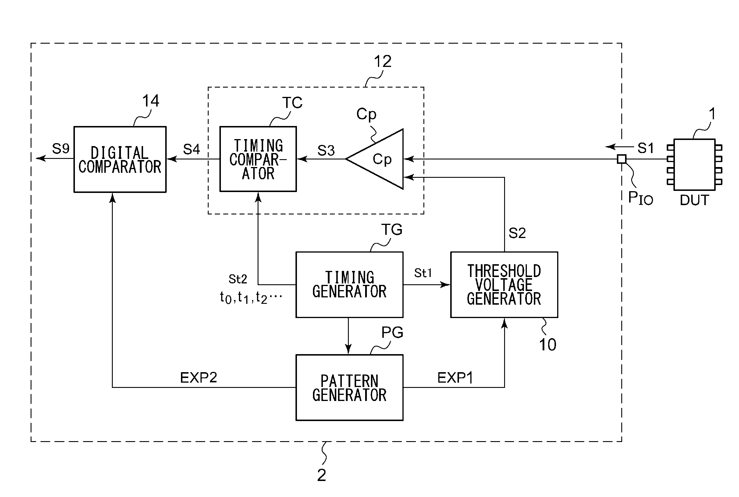
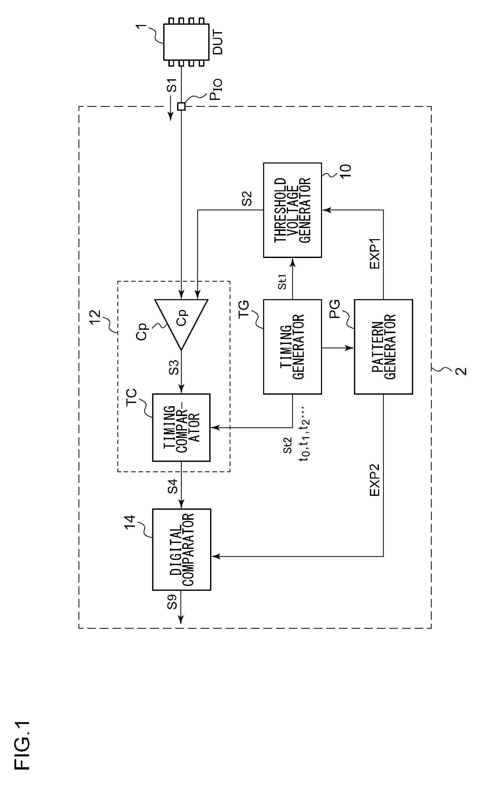
[0061]FIG. 1 is a block diagram which shows a configuration of a test apparatus 2 according to a first embodiment. The test apparatus 2 shown in FIG. 1 includes multiple I / O terminals PIO respectively provided to I / O ports of the DUT 1. The test apparatus 2 is arranged such that its I / O ports PIO are each connected to a corresponding I / O port of the DUT 1 via a transmission path, and such that a multi-valued signal S1 is input to each I / O port from the DUT 1. The number of I / O ports PIO can be determined as desired. In a case in which the DUT 1 is configured as memory or an MPU, the number of I / O ports is from several tens to a hundred or more. However, for ease of understanding and simplicity of description, the drawing shows only a single I / O port PIO and a block that corresponds to the single I / O port PIO.

[0062]The test apparatus 2 includes a pattern generator PG, a timing generator TG, a comparator unit 12, a threshold voltage generator 10, and a digital comparat...

Example

Second Embodiment

[0079]FIG. 4 is a block diagram which shows a test apparatus 2a according to a second embodiment. In the following description of the embodiment, the same configuration as that of the first embodiment will be omitted as appropriate, and description will be made mainly with reference to the points of difference from the first embodiment.

[0080]The test apparatus 2a shown in FIG. 4 includes multiple threshold voltage generators 10 and multiple comparators 12 for each I / O pin PIO. FIG. 4 shows an arrangement in which two threshold voltage generators 10H and 10L and two comparator units 12H and 12L are arranged for each I / O pin PIO.

[0081]The multiple threshold voltage generators 10H and 10L are configured to generate different respective threshold voltage sequences S2H and S2L. Specifically, the threshold voltage sequences S2H and S2L are generated such that the expected voltage level VEXP is set between them at each strobe timing. For the expected voltage level VEXPi to...

Example

Third Embodiment

[0088]FIG. 6 is a block diagram which shows a configuration of a test apparatus 2b according to a third embodiment. The test apparatus 2b shown in FIG. 6 has a configuration in which multiple threshold voltage generators 10 and multiple comparator units 12 are arranged for each I / O pin PIO, in the same way as the test apparatus 2a shown in FIG. 4.

[0089]The multiple comparator units 120 and 121 assigned to the same input pin PIO are each configured as an interleaving comparator which operates in a time sharing manner. Specifically, at the odd-numbered strobe timings t1, t3, and so forth, the comparator unit 120 is configured to compare the voltage level VDUT of the signal under test S1 with the threshold voltage Vth0 received from the threshold voltage generator 100. At the even-numbered strobe timings t0, t2, and so forth, the comparator unit 121 is configured to compare the voltage level VDUT of the signal under test S1 with the threshold voltage Vth1 received from ...


PUM


Abstract

A pattern generator PG generates control data which specifies a threshold voltage to be compared with a signal under test input to an I/O terminal, and generates expected value data which represents an expected value for the comparison result between the signal under test and the threshold voltage. A threshold voltage generator generates the threshold voltage having a voltage level that corresponds to the control data at every setting timing indicated by a first timing signal. A level comparator compares the voltage level of the signal under test with its corresponding threshold voltage. A timing comparator latches the output of the level comparator at a strobe timing indicated by a second timing signal so as to generate a comparison signal. A timing adjustment unit adjusts the phase of the first timing signal.

Description

BACKGROUND OF THE INVENTION[0001]1. Field of the Invention[0002]The present invention relates to a test apparatus.[0003]2. Description of the Related Art[0004]In conventional digital wired communication, a binary transmission method using time division multiplexing (TDM) has been the mainstream. In this case, high-capacity transmission has been realized by parallel transmission or high-rate transmission. In order to overcome the physical limitations on parallel transmission, serial transmission, which is high-speed transmission, is performed at a data rate of several Gbps to 10 Gbps or more using a high-speed interface (I / F) circuit. However, the data rate acceleration also has a limit, leading to a problem of BER (Bit Error Rate) degradation due to high-frequency loss or reflection in the transmission line.[0005]On the other hand, with the digital wireless communication method, multi-bit information carried by a carrier signal is transmitted and received. That is to say, the data r...

Claims


Application Information

Patent Timeline
IPC IPC(8): G06F19/00
CPCG01R31/31932G01R31/31725
Inventor ISHIDA, MASAHIROICHIYAMA, KIYOTAKA
Owner ADVANTEST CORP
Why Eureka
Try Eureka