Hair care apparatus

Inactive Publication Date: 2012-12-27
PALOCK
View PDF19 Cites 12 Cited by
  • Summary
  • Abstract
  • Description
  • Claims
  • Application Information

AI Technical Summary

Benefits of technology

[0016]According to another aspect of the present invention there is provided a method of forming a dreadlock on a person from a strand of hair or from a part of the strand, preferably the part of the strand closest to the scalp of the person. The method comprises separating a strand of hair from surrounding hair, using a holder of a dreadlocking apparatus to engage with the strand of hair so that a distal

Problems solved by technology

This is labour as well as cost intensive.
It is moreover

Method used


Image

  • Hair care apparatus
  • Hair care apparatus
  • Hair care apparatus

Examples


Embodiment Construction

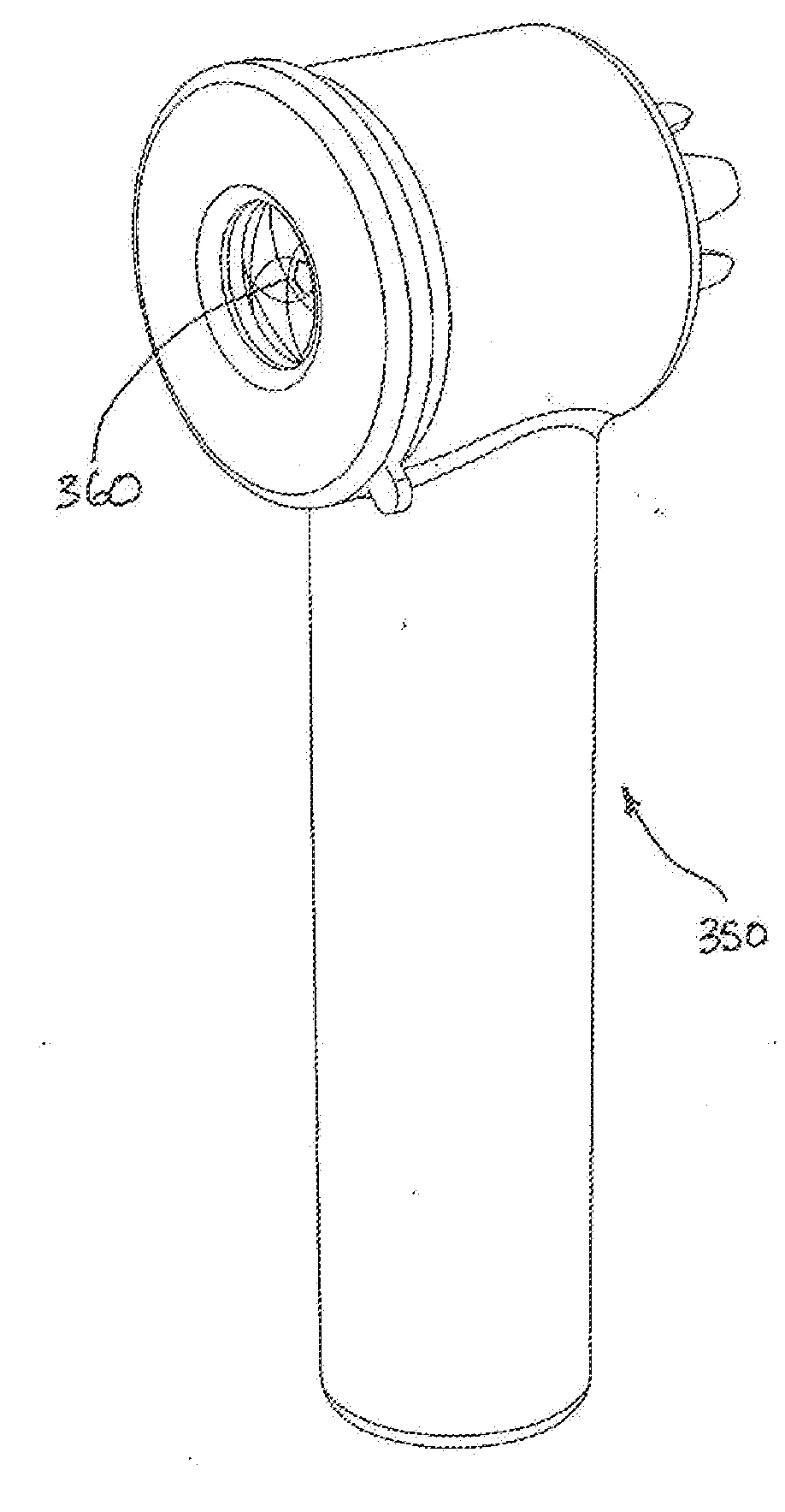
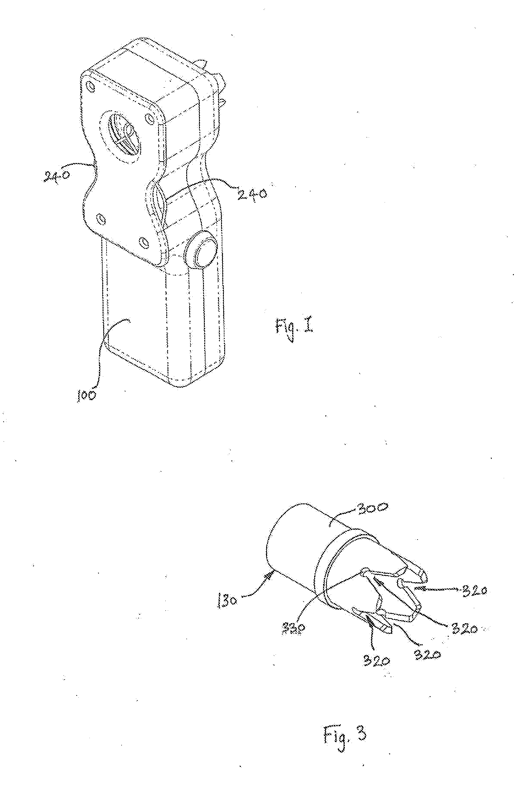
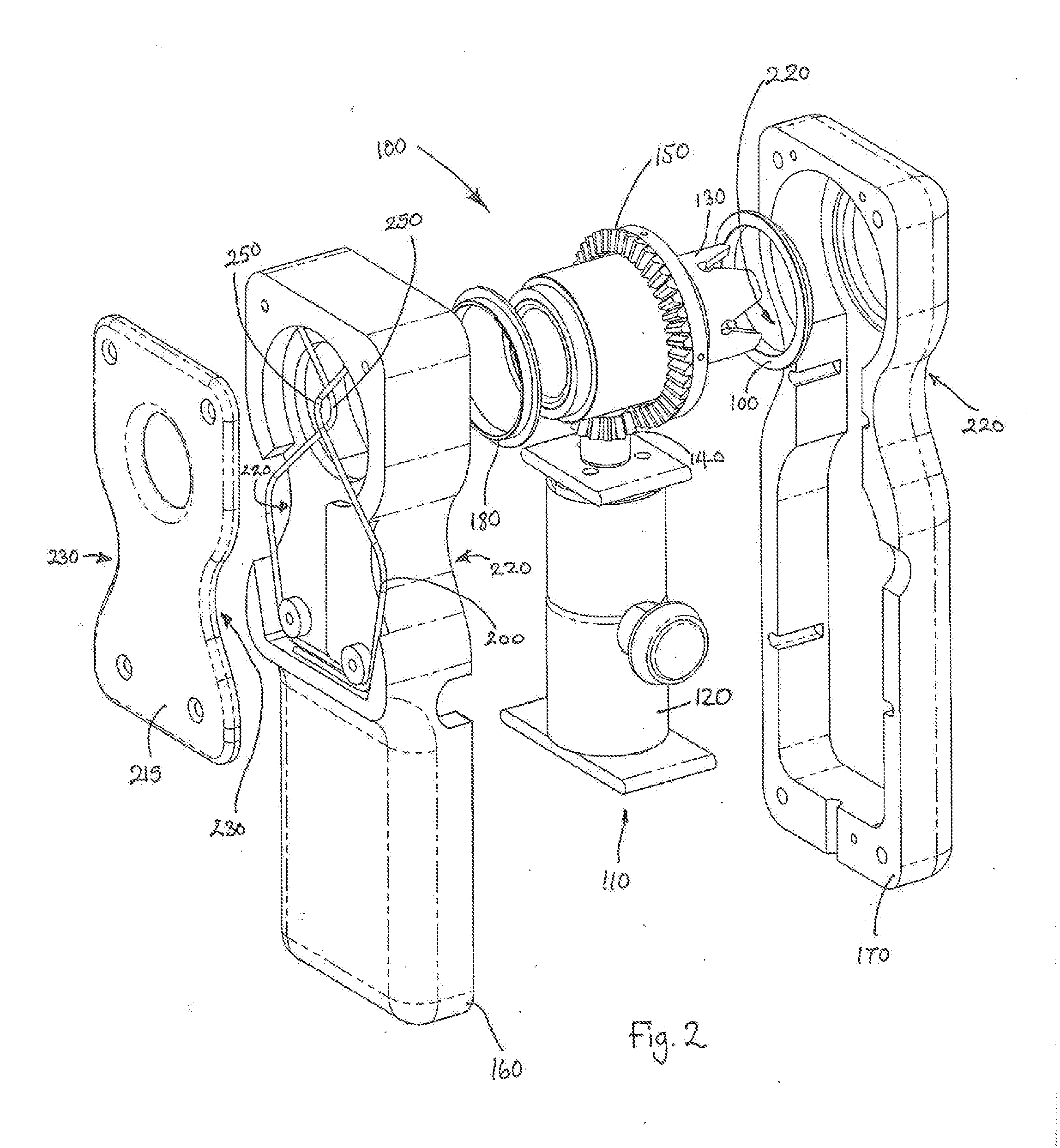
[0024]FIG. 1 shows a first apparatus 100 according to an embodiment. Details of the apparatus 100 are shown in the explosion diagram of FIG. 2. At the centre of the apparatus is a unit 110 that comprises both the motor 120 and the holder 130 for the strand of hair. As can be seen from FIG. 2 in this embodiment the motor forms part of a handle portion of the apparatus 100. Connected to the motor 120 is a first bevel gear 140. The motor 120 causes the first bevel gear 140 to rotate about its axis (which in FIG. 2 is the vertical axis). The bevel gear 140 in turn drives a second bevel gear 150. The second bevel gear 150 is fixedly attached to the holder 130 and rotates, together with the holder 130, about the longitudinal axis of the holder 130. Transmission of motion from the motor 120 to the holder 130 in this fashion provides the advantage that the spaces on either side of the holder 130 is not occupied by the motor, so that the strand of hair that is to be locked can be freely inse...


PUM


Abstract

An apparatus for dreadlocking hair comprising a motor and a means for holding or engaging a strand of hair. The holding means is rotated by the motor, so that the strand of hair is twisted into a dreadlock, that is, a twisted bundle of hair where hair on the surface of the bundle describes a purely helical path, at least in a newly dreadlocked part of the strand.

Description

CROSS-REFERENCE TO RELATED APPLICATION[0001]This application claims the benefit under 35 U.S.C. §119 of Great Britain Patent Application Serial No. 1106950.7, filed in Great Britain on Apr. 21, 2011, entitled “Hair Care Apparatus.”COPYRIGHT[0002]A portion of the disclosure of this patent document contains material which is subject to copyright protection. The copyright owner has no objection to the facsimile reproduction by anyone of the patent disclosure, as it appears in the Patent and Trademark Office patent files or records, but otherwise reserves all copyright rights whatsoever.FIELD OF THE INVENTION[0003]Embodiments relates to apparatus for dreadlocking hair.BACKGROUND[0004]Hair can be arranged in dreadlocks (hereinafter referred to as locking) manually by holding a strand of hair with one hand close to the scalp and by twisting a distal part of the strand of hair with another hand. When referring to a strand of hair reference is being made to more than one hair in a bundle. I...

Claims


Application Information

Patent Timeline
IPC IPC(8): A45D44/00
CPCA45D2/02A45D2007/004A45D7/00
Inventor SANSOLE, PALESAPETERSEN, HANS HENRIKRUSSELL, ANDREW ROBERT-JAMESMCBRIEN, RODERICKREDSHAW, DIGBYBOWKER, NEIL
Owner PALOCK
Why Eureka
Try Eureka