Cooling device

a cooling device and cooling technology, applied in indirect heat exchangers, lighting and heating apparatus, heat exchange apparatus, etc., can solve the problem of further affecting the function of the cooling device in the transportation of working fluid, which is required for the cooling device to be deactivated, and achieves spectacular improvement of capillary attraction, the effect of improving the performance of the cooling device and maximizing the capillary attraction

Inactive Publication Date: 2012-12-27
TOSHIBA HOME TECHNOLOGY
View PDF12 Cites 17 Cited by
  • Summary
  • Abstract
  • Description
  • Claims
  • Application Information

AI Technical Summary

Benefits of technology

[0023]According to the sixth aspect of the present invention, there can be provided the cooling device in which the capillary attraction is so strong as to be unaffected by gravity so that it is further hard for the function in the transportation of the working fluid to deteriorate owing to the enough flow volume of the working fluid. Further, the capillary attraction is spectacularly improved, permitting the performance of the cooling device to be improved.
[0024]According to the seventh aspect of the present invention, the capillary attraction is maximized, permitting the performance of the cooling device to be further improved.
[0025]According to the eighth aspect of the present invention, a gas phase and a liquid phase can be freely exchanged therebetween, permitting the performance of the cooling device to be further improved.
[0026]According to the ninth aspect of the present invention, there can be provided the cooling device in which the capillary attraction is so strong as to be unaffected by gravity so that it is further hard for the function in the transportation of the working fluid to deteriorate owing to the enough flow volume of the working fluid. Further, the capillary attraction is maximally improved and the thick of the sheet is reduced to the utmost extent. Furthermore, the capillary attract

Problems solved by technology

Further, the flow volume just enough for the working fluid to be prevented from drying out by its evaporation can be sufficiently maintai

Method used


Image

  • Cooling device
  • Cooling device
  • Cooling device

Examples


first embodiment

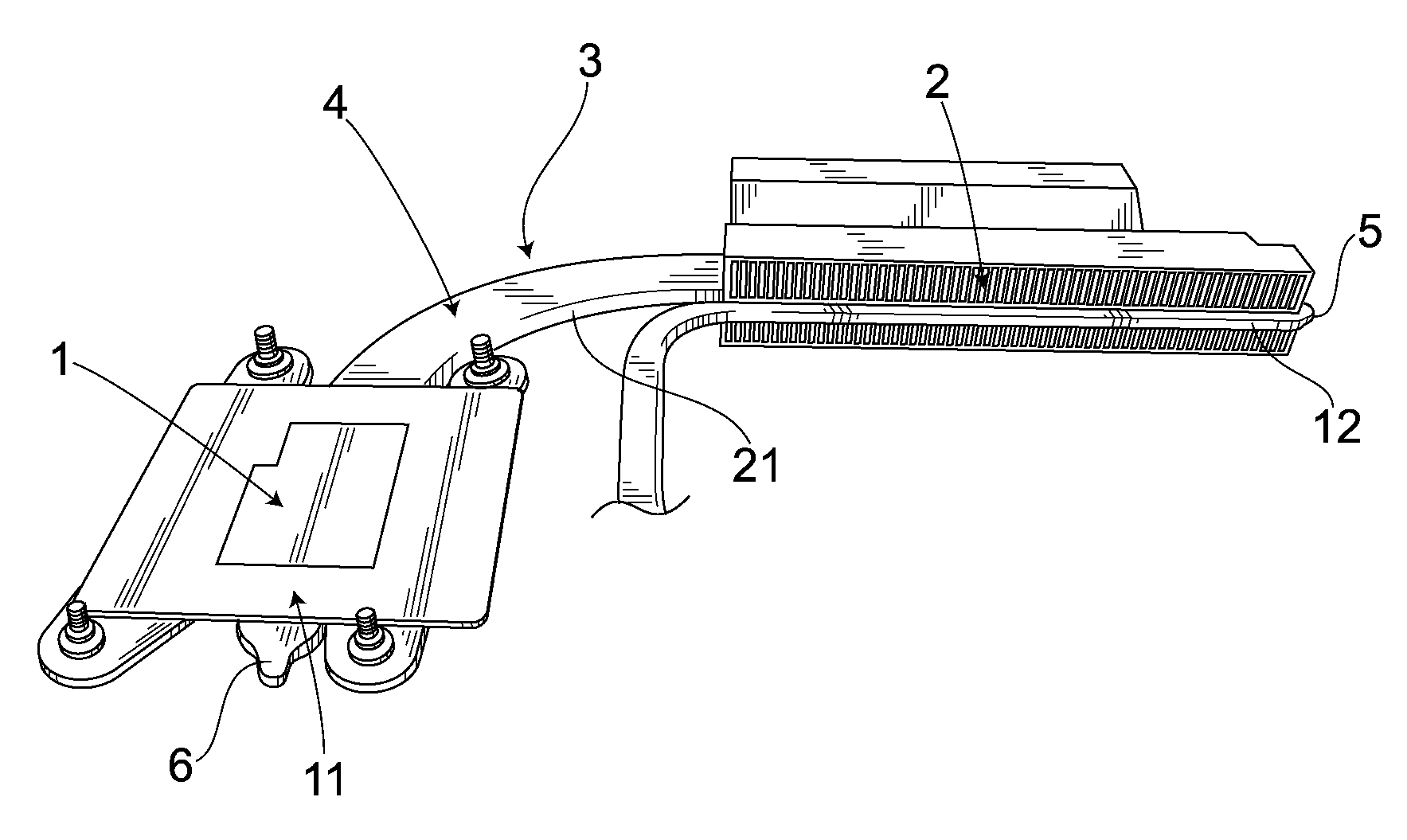
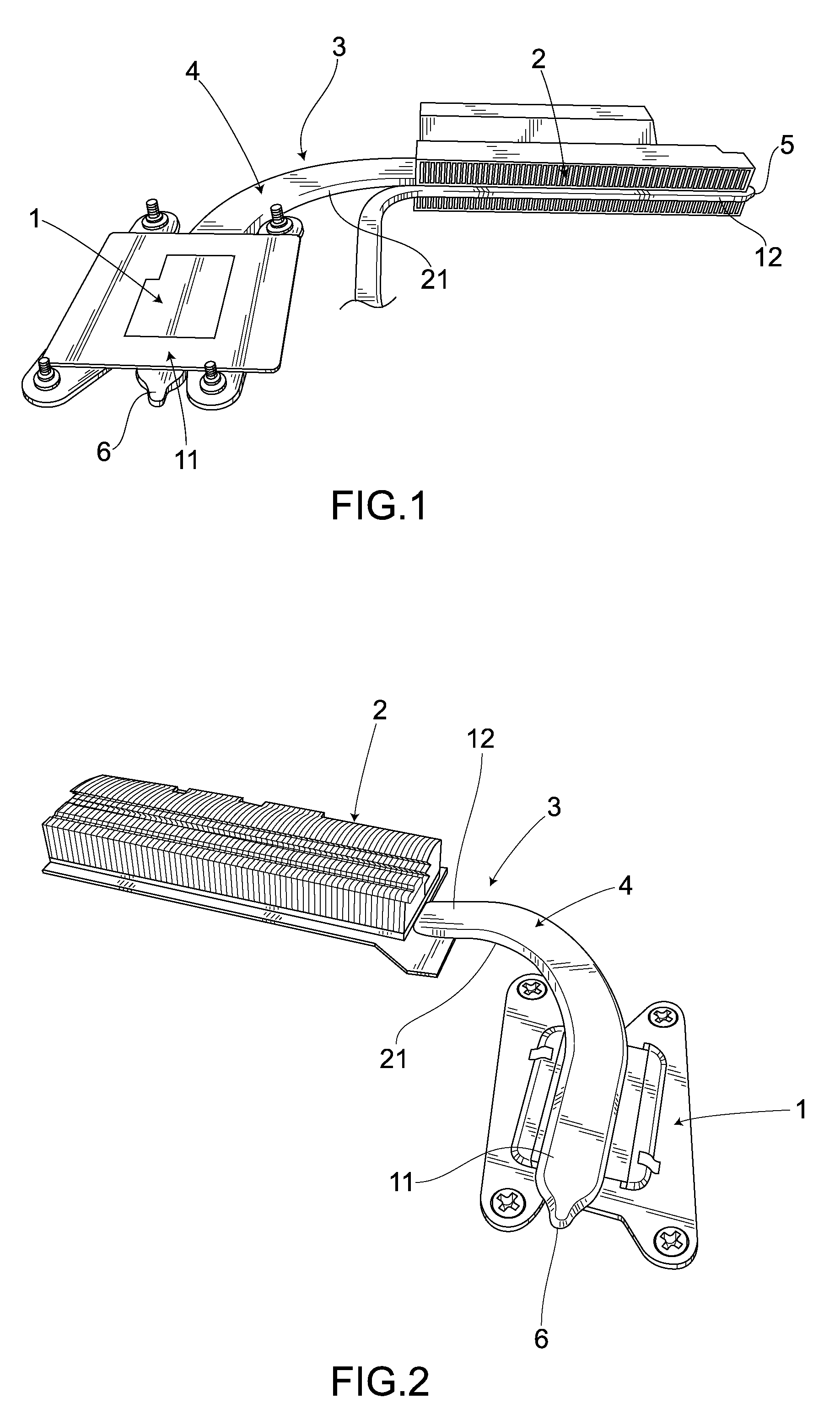
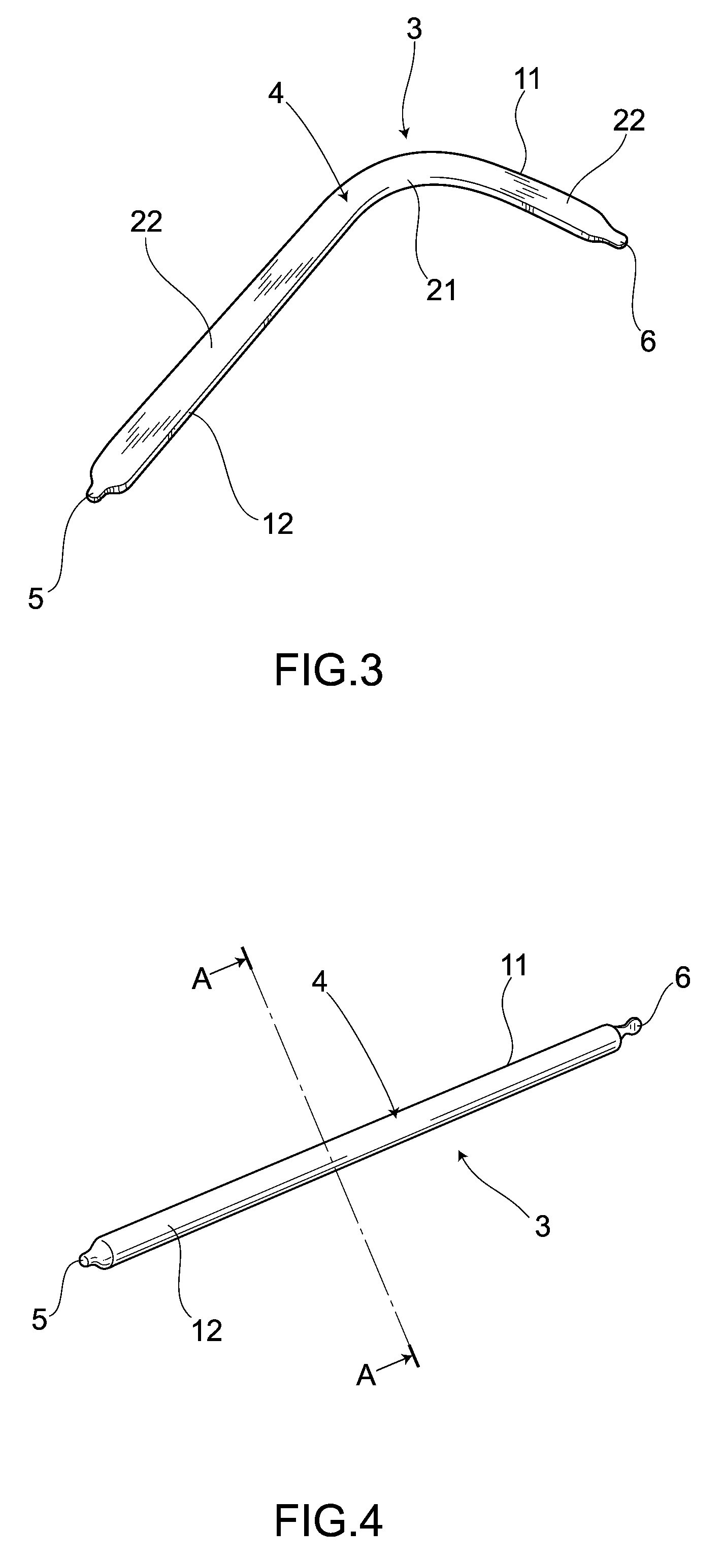
[0063]FIG. 5 to FIG. 10 show heat sink unit according to the present invention. Specifically, FIG. 5 shows a cross-sectional view orthogonal to the longitudinal direction of the heat pipe 3 shown in FIG. 4. In FIG. 5, the inner wall of the container 4, shown here, is formed into a smooth curved surface 16 without irregularities and the copper fiber assembly 8 acting as a fiber assembly with a wicked structure is hermetically housed inside the heat pipe 3 so as to be attached closely to the curved surface 16. The copper fiber assembly 8 is uniformly mounted without a break in mid-course from one end of the heat pipe 3 to the other end thereof. Then, inside the heat pipe 3, there are provided a first flow path 17 formed inside the copper fiber assembly 8 to transfer purified water (not shown), acting as a working fluid condensed in the heat dissipating section 12, toward the heat receiving section 11, and a second flow path 18 formed in a region surrounded by the copper fiber assembl...

second embodiment

[0096]In this embodiment, the inner structure of the heat pipe 3 is different from that in the Specifically, as shown in FIG. 14, as a substitute for the tube 10 produced by weaving the copper fibers 28, a sheet 30 is employed onto which the copper fibers 28 are sintered. The copper fibers 28 employed here are mounted on the inside of the container 4 of the heat pipe 3 so as to be attached closely to the insides of the grooves 19.

[0097]In FIG. 15 and FIG. 16, both show a structure of a single sheet 30 housed inside the heat pipe 3. The sheet 30 is produced by processing a plurality of copper fibers 28 unidirectionally-aligned in layers into a sheet using a sintering process. In order to enhance the capillary attraction of the copper fibers 28, the sheet 30 is arranged so that the copper fibers 28 are unidirectionally arranged along the longitudinal direction of the heat pipe 3.

[0098]In order to manufacture the heat pipe 3 as shown in FIG. 14, firstly, the sheet 30 is rolled up into...

third embodiment

[0131]In addition, the present invention is not limited to the above embodiments and various modifications are possible without departing from the gist of the present invention. The cooling device shown in each embodiment, e.g., can be incorporated in other various devices requiring a cooling operation than a personal computer. Further, a working fluid different from the purified water can be housed and sealed inside the heat pipe 3. Furthermore, in common with each embodiment, considering, as a condition for the heat pipe 3, the large thermal conductivity for thermal transportation, the corrosion resistance to sealed water, hydrophilicity, the adequacy for a sintering process, and the formation of the pipe and the fiber using the same material, copper is the best for the materials of the heat pipe 3, the copper fiber assembly 8, the tube 10, the sheet 30, the unwoven fabric 42, and the sintered sheet 43. Other metals than copper such as aluminum, SUS (stainless steel) or the like, ...


PUM


Abstract

There is provided a cooling device not affected by gravity by exerting a strong capillary attraction to be hard to deteriorate in transportation function. Unidirectionally-aligned copper fiber assembly 8 is mounted, by a sintering process, on an inner wall of a heat pipe 3 along the longitudinal direction of the heat pipe 3. Therefore, by a strong capillary attraction caused by fine copper fiber assembly 8, purified water can be transported without being affected by gravity. A flow volume just enough for the purified water to be prevented from drying out by its evaporation can be maintained, thus making it hard for a function in the transportation of the purified water to be deactivated. Further, the unidirectionally-aligned copper fiber assembly 8 is mounted along the longitudinal direction of heat pipe 3 and hence the purified water smoothly flows in the longitudinal direction of heat pipe 3.

Description

BACKGROUND OF THE INVENTION[0001]1. Field of the Invention[0002]The present invention relates to a cooling device which is suitable for cooling a heat source and enables a large amount of heat transportation despite its compact size.[0003]2. Description of the Related Art[0004]Heretofore, there has been known a cooling device utilizing a capillary attraction effected by grooves and copper powders as a result of forming the grooves on an inner wall of a pipe and sintering the copper powders on the inner wall of the pipe to carry a working fluid condensed in a heat dissipating section to a heat receiving section (e.g., Japanese unexamined patent application publication No. 2006-284020).[0005]The conventional structure, however, functions poorly in carrying a working fluid from the heat dissipating section to the heat receiving section. In other words, the capillary attraction is weak in a cooling device formed with the grooves on the inner wall of the pipe, halting, in some cases, a f...

Claims


Application Information

Patent Timeline
IPC IPC(8): F28D15/04
CPCF28F21/084F28F2255/18F28D15/046F28D15/0275
Inventor HONMURA, OSAMUKOJIMA, NOBUYUKISAKUMA, NAOTOITO, NOBUO
Owner TOSHIBA HOME TECHNOLOGY
Why Eureka
Try Eureka