Position Corrected Pulse Width Modulation for Brushless Direct Current Motors

a direct current motor and pulse width technology, applied in the direction of motor/generator/converter stopper, electronic commutator, dynamo-electric converter control, etc., can solve the problem of not being able to recognize physical differences in the motor, unable to achieve uniform torque output of the motor, and unable to achieve the effect of reducing motor audible noise, improving motor efficiency, and improving motor efficiency

Active Publication Date: 2012-12-27
AGAVE SEMICON
View PDF5 Cites 35 Cited by
  • Summary
  • Abstract
  • Description
  • Claims
  • Application Information

AI Technical Summary

Benefits of technology

[0008]By adjusting the width of pulses that make up a motor command signal during a commutation period of a motor cycle, operation of a motor may be improved. In particular, adjusting pulse widths of individual pulses that form a pulse train delivering energy to a motor can improve motor efficiency, reduce motor audible noise, and improve torque output characteristics of the motor. In one example, the first few pulses that are included in the pulse train of a motor commutation interval have a shorter duration (e.g., the amount if time a signal is high is shorter than the amount of time the signal is low during the period of a pulse). As the commutation interval continues, the pulses increase in duration for a time during the motor commutation interval. Finally, the pulse duration is decreased near the end of the motor commutation interval. This pulse train generating strategy can account for the position of motor poles during motor rotation in adjusting the pulse width so that attraction and repulsion between motor poles is improved and made more efficient, at least during some conditions.

Problems solved by technology

Linear voltage regulators are also used to vary the DC voltage across BLDC motors; but they have the disadvantage of power losses across their pass elements.
For example, the energy is applied in the same manner throughout one rotation of the rotor and therefore fails to recognize physical differences in the motor that are related to rotor position.
Thus, applying power to a motor in this manner can produce non-uniform torque output from the motor, increased audible noise from the motor, and energy losses that are higher than is desirable.

Method used


Image

  • Position Corrected Pulse Width Modulation for Brushless Direct Current Motors
  • Position Corrected Pulse Width Modulation for Brushless Direct Current Motors
  • Position Corrected Pulse Width Modulation for Brushless Direct Current Motors

Examples


Embodiment Construction

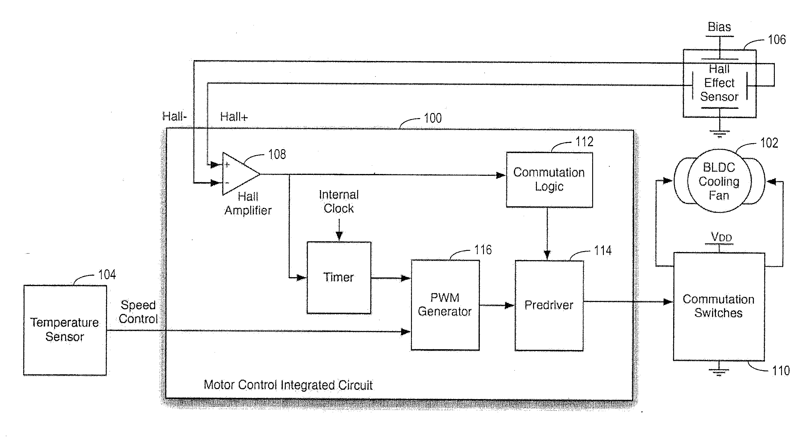
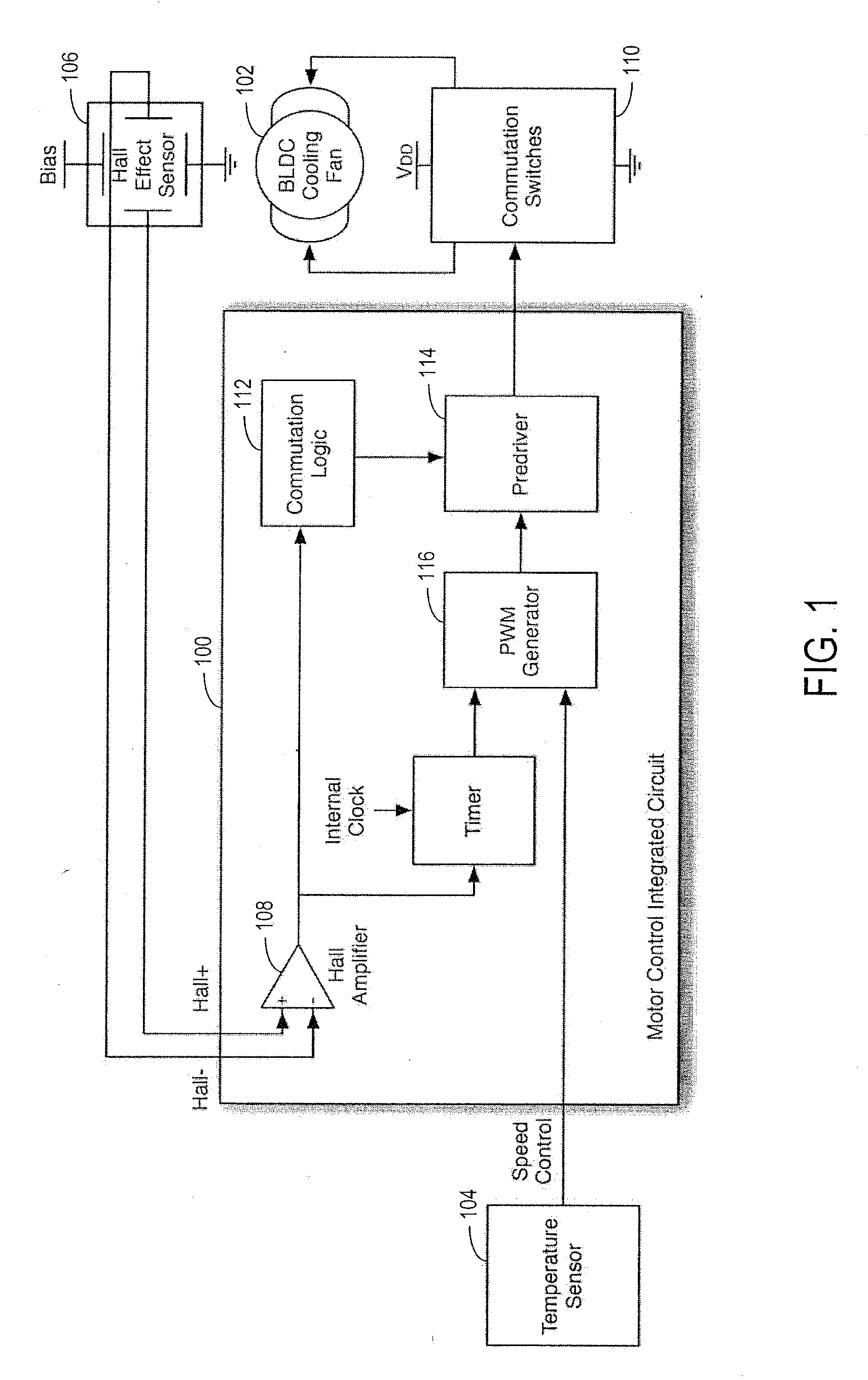
[0021]FIG. 1 shows a block diagram of a typical application for a motor control integrated circuit 100. In this example the brushless direct current (BLDC) motor 102 is a cooling fan, although it could be any BLDC motor. In the cooling fan application a temperature sensor 104 reports the system temperature to motor control integrated circuit (IC) 104 in the form of a speed control signal representing the desired speed for the fan. The differential output of a Hall Effect Sensor 106 gets amplified by a Hall Amplifier 108 to determine how the rotor's magnetic poles, north and south, are oriented with respect to the stator. Commutation Switches 110 connect the fan's motor windings to the power supply (labeled VDD) and ground. The motor control IC 100 uses the magnetic pole information together with Commutation Logic block 112, Pre-Driver 114, and Commutation Switches 110 to commutate the current in the stator windings. A pulse width module (PWM) Generator 116 adjusts the PWM duty cycle...


PUM


Abstract

A method of operating a brushless direct current motor is provided that generates a rotor position dependent pulse width modulation waveform. The waveform can improve motor efficiency and reduce torque variation.

Description

CROSS REFERENCE TO RELATED APPLICATIONS[0001]This application is a continuation-in-part of International Patent Application Serial No. PCT / US2011 / 026743, filed Mar. 1, 2011 and entitled POSITION CORRECTED PULSE WIDTH MODULATION FOR BRUSHLESS DIRECT CURRENT MOTORS, which claims priority to U.S. Provisional Patent Application Ser. No. 61 / 309,791, filed Mar. 2, 2010 and entitled POSITION CORRECTED PULSE WIDTH MODULATION FOR BRUSHLESS DIRECT CURRENT MOTORS, the entirety of both of which are hereby incorporated herein by reference for all intents and purposes.FIELD[0002]This description is directed to motor controllers for brushless direct current motors. In particular, a system and method for generating pulse width modulated motor control commands is disclosed.BACKGROUND AND SUMMARY[0003]Pulse width modulation (PWM) is a common technique used to control the average speed of brushless direct current (BLDC) motors. Direct current motors have a characteristic that their speed is nearly lin...

Claims


Application Information

Patent Timeline
Patent Type & Authority Applications(United States)
IPC IPC(8): H02P6/10H02P6/20
CPCH02P6/18H02P6/28H02P6/153H02P6/10H02P6/14H02P6/16
Inventor BRANNEN, ROBERT ALAN
Owner AGAVE SEMICON
Why Eureka
Try Eureka