Illumination control

a technology of illumination optics and control, applied in the direction of optical radiation measurement, instruments, photomechanical equipment, etc., can solve the problems of reducing throughput, low source brightness and mask complexity, and overcoming obstacles, so as to achieve the effect of enhancing contras

Active Publication Date: 2012-12-27
KLA TENCOR TECH CORP
View PDF3 Cites 31 Cited by
  • Summary
  • Abstract
  • Description
  • Claims
  • Application Information

AI Technical Summary

Benefits of technology

[0067]Coherence coding can enhance contrast and is also a prerequisite for coherent polarization coding and coherent phase coding. Coherence coding can also be used to effect suppression in narrow bandwidth illumination. In one implementation the illumination source may be a super-continuum source. As used herein, a super-continuum source generally refers to a source of illumination having a short longitudinal coherence length (e.g., about 2.5μ) and a long spatial coherence, e.g., several millimeters. However, it is noted

Problems solved by technology

The latter three technologies are still in their infancy relative to optical lithography and still have obstacles to overcome, including decreased throughput, low source brightness and mask complexity, respectively.
Due to manufacturing limitations most optical elements have plane, spherical or paraboloidal form.
The restriction to surfaces of simple form imposes limitations in an optical system

Method used


Image

  • Illumination control
  • Illumination control
  • Illumination control

Examples


Embodiment Construction

[0015]Although the following detailed description contains many specific details for the purposes of illustration, anyone of ordinary skill in the art will appreciate that many variations and alterations to the following details are within the scope of the invention. Accordingly, the examples of embodiments of the invention described below are set forth without any loss of generality to, and without imposing limitations upon, the claimed invention.

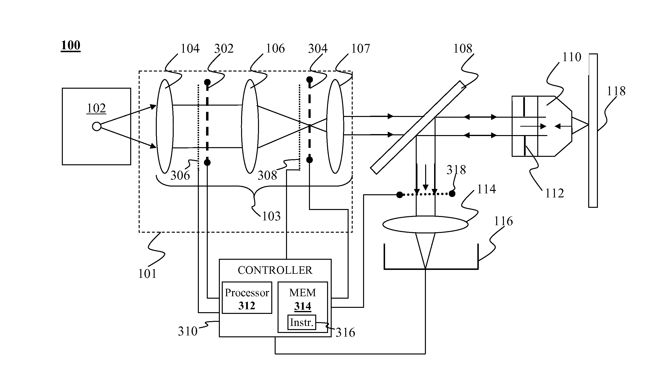
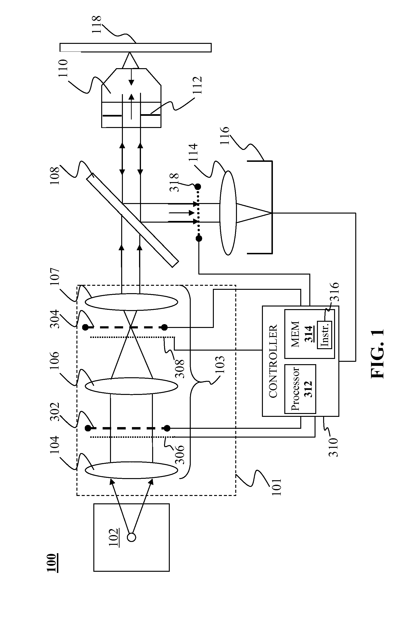
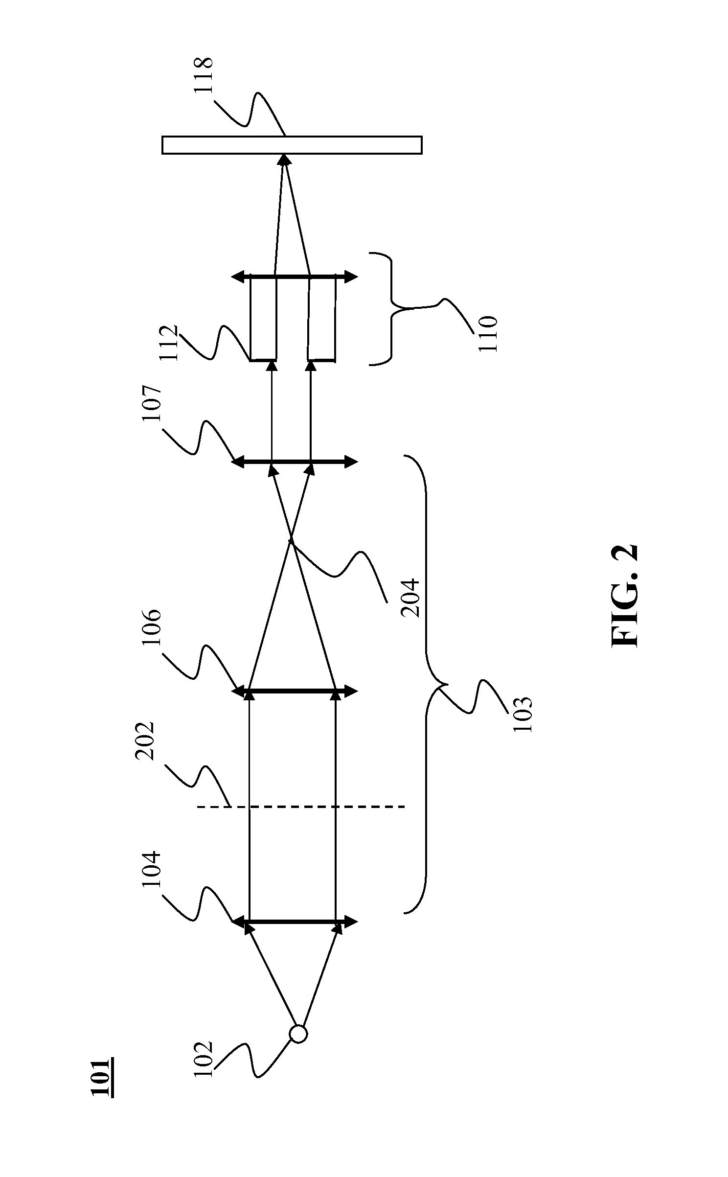
[0016]The objective of traditional illumination methods is to deliver best possible illumination spot, in terms of spatial and angular distribution, to the target so that the illumination system contribution to the overall error will be limited. However, illumination source and optics can introduce aberrations that upon reflection from the target result in overall lower quality than the collection optics quality. And inversely, no attempt is made to compensate for collection optics flaws with illumination control. The assumption of perfect...


PUM


Abstract

An optical system may include an objective, a source of illumination, an illumination system having illumination optics configured to direct the illumination onto the objective, and at least two dynamic optical array devices located at a pupil conjugate plane and a field conjugate plane, respectively in the illumination optics. The dynamic optical array devices are configured to control one or more properties of illumination coupled from the illumination system to the objective.

Description

FIELD OF THE INVENTION[0001]Embodiment of this invention generally relates to optical overlay metrology and more particularly to control of illumination optics in an overlay system.BACKGROUND OF THE INVENTION[0002]Lithography is a key factor in the drive for higher levels of microcircuit integration. Dynamic RAMs have quadrupled in the level of integration every three years as a result of the reduction in minimum geometries and increases in chip size. As minimum geometries become smaller, alternatives to optical lithography, such as electron beam direct write, X-ray and electron / ion beam proximity technologies become attractive. The latter three technologies are still in their infancy relative to optical lithography and still have obstacles to overcome, including decreased throughput, low source brightness and mask complexity, respectively.[0003]While optical lithography continues to be the dominant technology because it is well established and is capable of implementing sub-micron ...

Claims


Application Information

Patent Timeline
IPC IPC(8): G02B26/00G02F1/01G02F1/29G02F1/00
CPCG01J1/4257G02B26/0833G02B27/0068G02B26/06G02B21/0016G02B21/082G02B21/365G03F7/70633G02B27/18H01L21/0274
Inventor MANASSEN, AMNONSELIGSON, JOELSAPIENS, NOAM
Owner KLA TENCOR TECH CORP
Why Eureka
Try Eureka