Compact optical frequency comb systems

a comb system and optical frequency technology, applied in the direction of electrical equipment, laser details, active medium shape and construction, etc., can solve the problems of large component count, high cost, and relative difficulty in manufacture, and achieve the effect of facilitating the self-starting operation of passive modelocking and further extending the optical bandwidth of generated pulses

Active Publication Date: 2012-12-27
UNIV OF COLORADO THE REGENTS OF
View PDF6 Cites 27 Cited by
  • Summary
  • Abstract
  • Description
  • Claims
  • Application Information

AI Technical Summary

Benefits of technology

[0013]In another embodiment, the graphene film can also be used as a saturable absorber in order to facilitate passive modelocking Self-starting operation of modelocking can be further facilitated and Q-switching inside the laser resonator can be suppressed using loss modulation of the graphene film.
[0014]In order to generate short pulses with mode locked fiber lasers, dispersion compensation elements such as chirped fiber Bragg gratings or lengths of fiber with different dispersion parameters can be incorporated inside the resonator. In addition, simultaneous 2nd and 3rd order dispersion compensation can be implemented, which is particularly useful for the operation of passively mode locked fiber lasers at wavelengths >1700 nm. The optical bandwidth of the generated pulses can further be extended by using positive dispersion fibers with small core diameters in conjunction with negative dispersion fibers with larger core diameters, thus facilitating the oscillation of similariton or parabolic pulses inside the oscillator.

Problems solved by technology

However, to date, passively mode locked lasers and optical frequency combs or in particularly passively mode locked fiber lasers and fiber based frequency combs are still relatively difficult to manufacture, have a large component count and their high cost prevents their use in mass applications.

Method used


Image

  • Compact optical frequency comb systems
  • Compact optical frequency comb systems
  • Compact optical frequency comb systems

Examples


Embodiment Construction

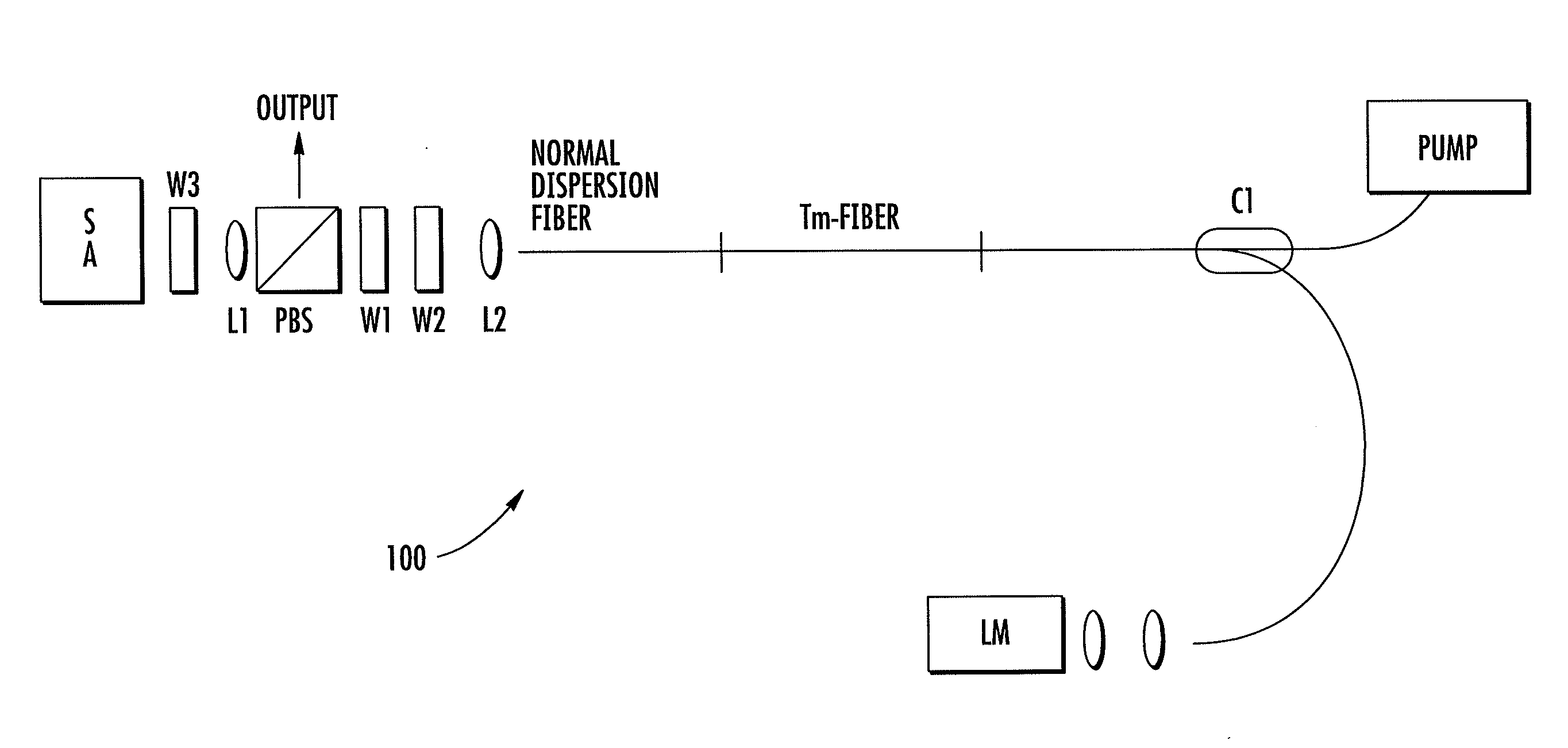
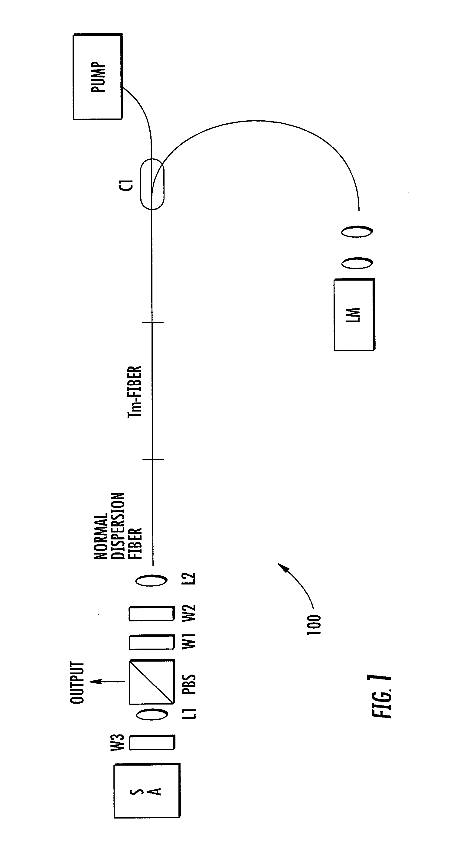
[0027]Several components of a passively mode locked fiber oscillator 100 optimized for the generation of short pulses and broad coherent spectra are shown in FIG. 1. In an exemplary embodiment, a Tm-doped silica fiber can be used as the gain medium, although any other rare-earth dopants are also possible. A Tm doped alumino-silicate fiber with a numerical aperture of NA=0.25 can be used which has negative dispersion at 1900 nm. The negative (soliton supporting) dispersion of the Tm fiber and the fiber pigtails produced by pump coupler C1 are compensated by a normal dispersion fiber. For pumping, a pump source emitting in the 1500-1650 nm wavelength range or near 790 nm can be conveniently used. The system comprises a Fabry-Perot configuration with a conventional semiconductor saturable absorber mirror SA on one cavity end and a plain gold mirror or a loss modulating mirror LM on the second distal end. Here only LM is shown. However, a conventional mirror can replace LM and be dispos...


PUM


Abstract

Compact optical frequency sources are described. The comb source may include an intra-cavity optical element having a multi-material integrated structure with an electrically controllable active region. The active region may comprise a thin film. By way of example, the thin film and an insulating dielectric material disposed between two electrodes can provide for rapid loss modulation. In some embodiments the thin film may comprise graphene. In various embodiments of a frequency comb laser, rapid modulation of the CEO frequency can be implemented via electric modulation of the transmission or reflection loss of an additional optical element, which can be the saturable absorber itself. In another embodiment, the thin film can also be used as a saturable absorber in order to facilitate passive modelocking. In some implementations the optical element may be formed on a cleaved or polished end of an optical fiber.

Description

FIELD OF THE INVENTION[0001]The invention relates to compact optical frequency comb systems and exemplary applications thereof.BACKGROUND[0002]High brightness broadband optical frequency comb sources have many applications in medicine, spectroscopy, microscopy, ranging, sensing and metrology. Such sources need to be highly robust, have long term stability, and also comprise a minimal component count with a high degree of optical integration for mass market applications. Especially, broadband optical frequency comb sources based on passively modelocked lasers in conjunction with frequency broadening or supercontinuum generation in highly nonlinear fibers or waveguides have generated of lot of interest. Particularly when used in conjunction with short pulse fiber lasers, an all-fiber system construction is possible for supercontinuum generation which results in benefits such as greatly simplified manufacturing routines, low cost and high levels of thermo-mechanical stability.[0003]Fib...

Claims


Application Information

Patent Timeline
Patent Type & Authority Applications(United States)
IPC IPC(8): H01S3/067H01S3/11
CPCH01S3/06712H01S3/06725H01S3/08059H01S3/105H01S3/1118H01S3/1115H01S3/0092H01S3/10046H01S3/1053H01S3/176H01S3/1616
Inventor FERMANN, MARTIN E.SCHIBLI, THOMAS R.HARTL, INGMAR
Owner UNIV OF COLORADO THE REGENTS OF
Why Eureka
Try Eureka