
Composite Pavement Structures

a pavement structure and composite material technology, applied in the field of composite pavement structures, can solve the problems of inconsistencies in the composite material, the composite material is required to be replaced at additional cost, and the working time of the composite material is further reduced once onsite, so as to improve the compressive strength, improve the bonding strength, and improve the physical properties.

Active Publication Date: 2013-01-10
BASF AG +1
View PDF9 Cites 16 Cited by
  • Summary
  • Abstract
  • Description
  • Claims
  • Application Information

AI Technical Summary

Benefits of technology

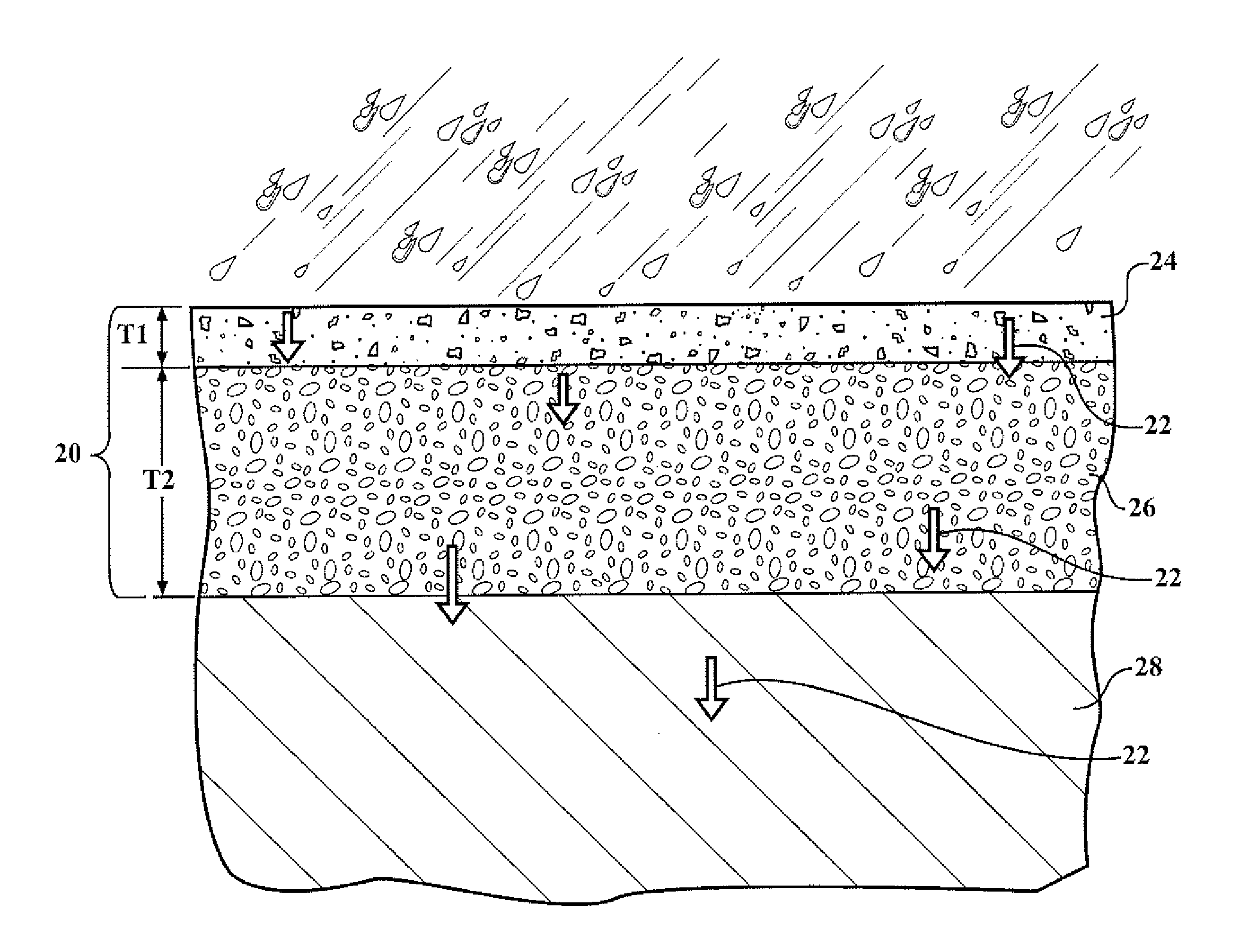
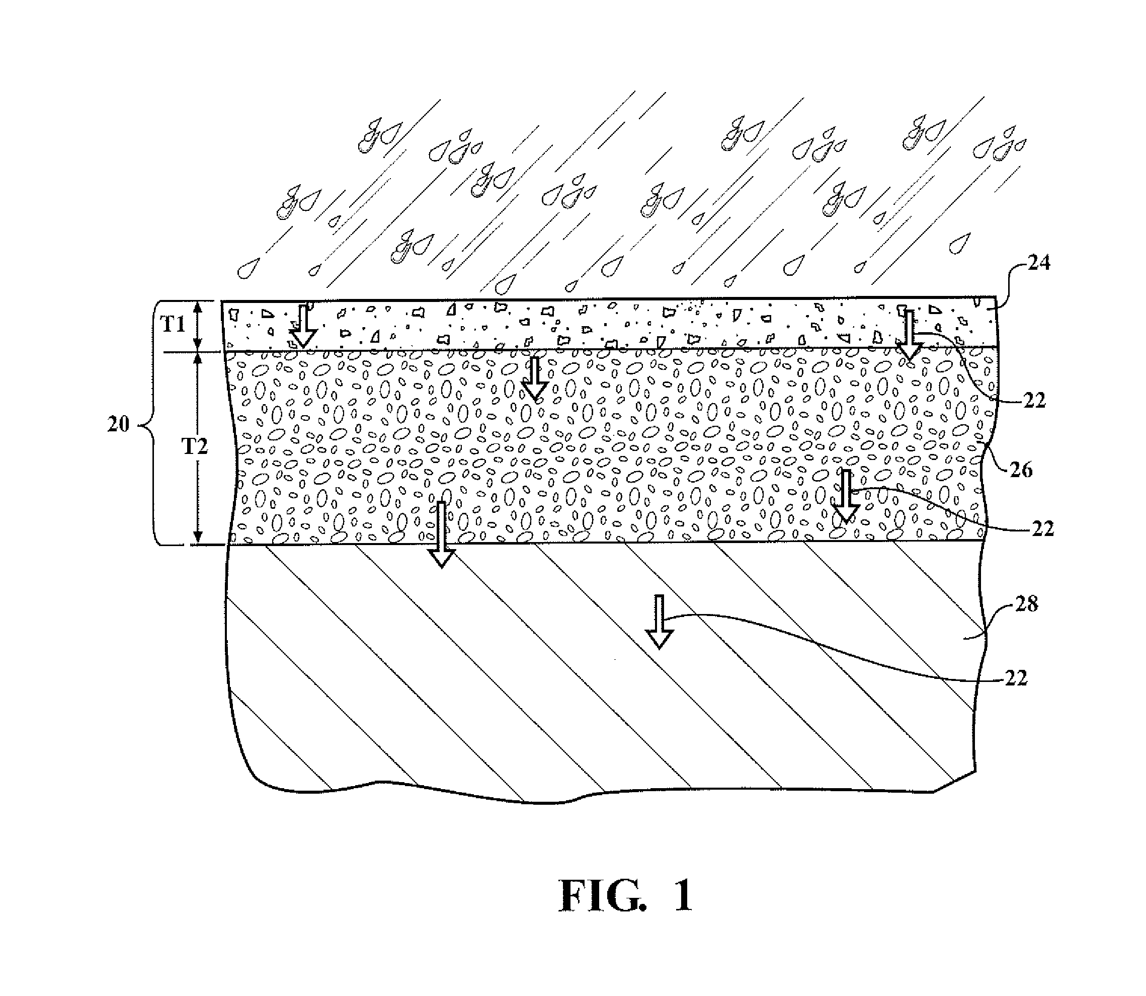
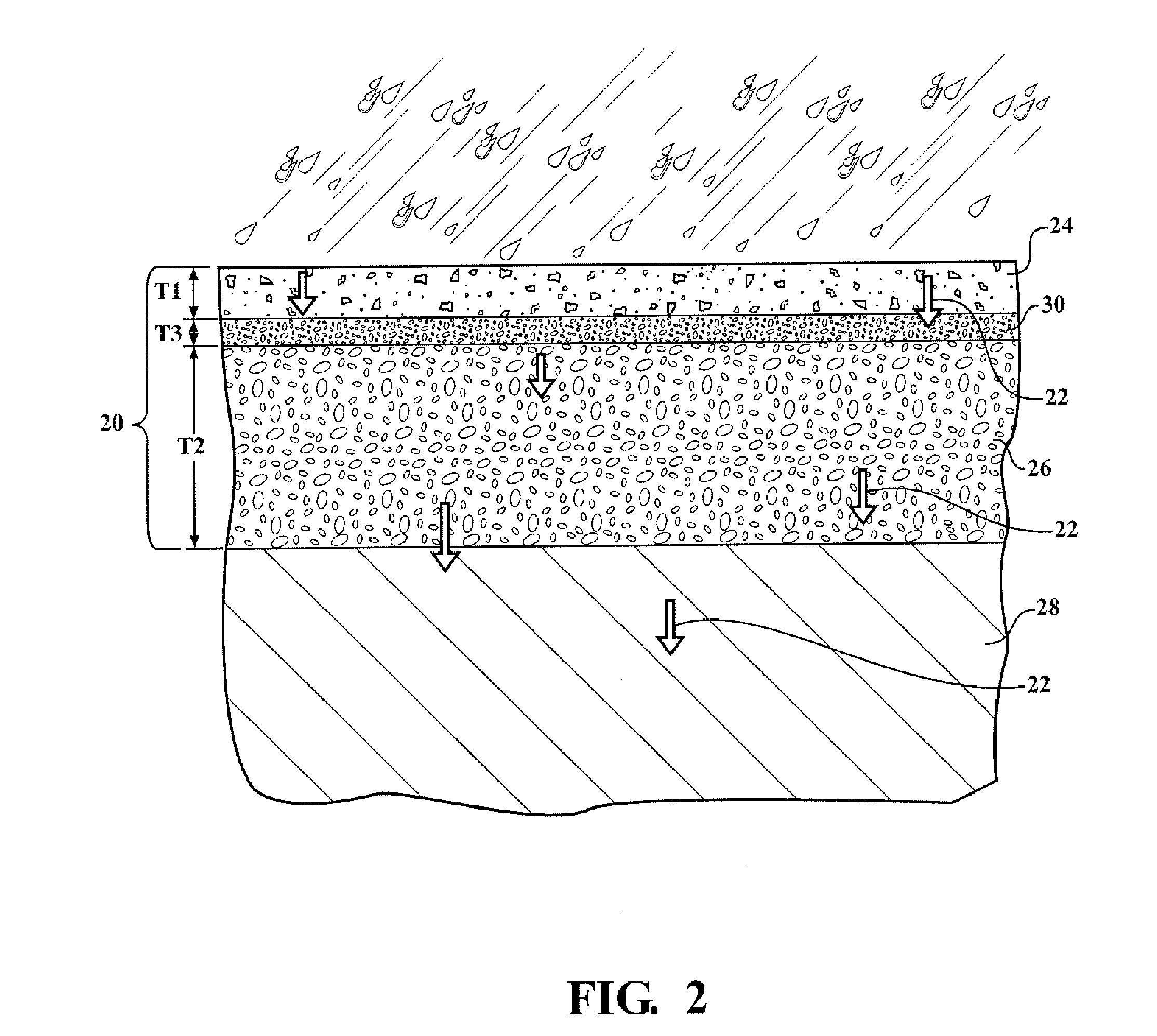
The elastomeric composition in this patent has good physical properties that make it useful for wearing layers of pavements. It improves the bonding between the elastomer and the aggregate, as well as increases the compressive, shear, and flexural strength of the layer, reducing the chances of the aggregate coming off. The composite pavement can be either non-porous or porous, which helps decrease water run-off and other issues associated with traditional pavements.

Problems solved by technology

Offsite production requires the composite material to be transported to a construction site thereby further decreasing working time of the composite material once onsite.
A significant drawback of such a method is an inconsistent coating of the aggregate, which creates inconsistencies in the composite material.
Inconsistencies in the composite material can result in early failure of the composite material thereby requiring the composite material to be replaced at additional cost.
In addition, such methods are time consuming.
A common form of failure of the composite material is spalling, where the aggregate loosens from the composite material, eventually dislodging from the composite material altogether.
A significant drawback of this process, commonly referred to as a batch process, is once again reduced working time since the binder composition begins to immediately cure once present in the batch mixer.

Method used


Image

  • Composite Pavement Structures
  • Composite Pavement Structures
  • Composite Pavement Structures

Examples


examples

[0150]Examples of the resin and isocyanate components of the system are prepared. Examples of the elastomeric composition are also prepared. The resin and isocyanate components are formed by mixing their respective components in a vessel. The vessel is a container capable of withstanding agitation and having resistance to chemical reactivity. The components of the resin and isocyanate components were mixed using a mixer for 1 to 3 minutes at 1000 to 3500 rpm. The resin and isocyanate components were mixed in a similar manner to form the elastomeric compositions.

[0151]The amount and type of each component used to form the Resin and Isocyanate Components are indicated in TABLES I and II below with all values in parts by weight (pbw) based on 100 parts by weight of the respective Resin or Isocyanate Component unless otherwise indicated. The symbol ‘-’ indicates that the component is absent from the respective Resin or Isocyanate Component.

TABLE IExample 1Example 2Example 3Resin Compone...


PUM

PropertyMeasurementUnit
diameteraaaaaaaaaa
thicknessaaaaaaaaaa
thicknessaaaaaaaaaa

Abstract

A composite pavement structure comprises a wearing course layer and a base course layer disposed below the wearing course layer. The wearing course layer comprises aggregate, e.g. glass and rock, and an elastomeric composition. The elastomeric camposition comprises the reaction product of an isocyanate component and an isocyanate-reactive component. The isocyanate component comprises a polymeric isocyanate, and optionally, an isocyanate-prepolymer. The isocyanate-reactive component comprises a hydrophobic polyol and a chain extender having at least two hydroxyl groups and a molecular weight of from about 62 to about 220. The chain extender is present in the isocyanate-reactive component in an amount of from about 1 to about 20 parts by weight based on 100 parts by weight of the isocyanate-reactive component. The base course layer comprises aggregate which is the same or different than the aggregate of the wearing course layer. Methods of forming the composite pavement structure are also disclosed.

Description

CROSS REFERENCE TO RELATED APPLICATIONS[0001]This application claims the benefit of U.S. Provisional Patent Application Ser. No. 61 / 288,637, filed on Dec. 21, 2009, which is incorporated herewith by reference in its entirety.FIELD OF THE INVENTION[0002]The present invention generally relates to a composite pavement structure comprising a wearing course layer comprising aggregate and an elastomeric composition, and more specifically to a composite pavement structure comprising a base course layer and a wearing course layer comprising aggregate comprising glass and an elastomeric composition comprising an isocyanate component comprising a polymeric isocyanate, and optionally, an isocyanate prepolymer, and the elastomeric composition further comprising an isocyanate-reactive component comprising a hydrophobic polyol and a chain extender, and to methods of forming the composite pavement structure.DESCRIPTION OF THE RELATED ART[0003]The use of composite materials to form articles such as...

Claims


Application Information

Patent Timeline
Patent Type & Authority Applications(United States)
IPC IPC(8): E01C11/00
CPCC03C12/00C08L75/04C03C17/3405C04B20/1051C04B26/16C04B2111/00284C04B2111/00293C04B2111/0075C04B2111/60C03C17/30C08L21/00C08K3/40C08K3/34Y10T428/25C04B14/22C04B40/065C04B2111/00612Y10T428/31551Y10T428/249984Y02W30/91C04B14/06C04B24/02C03C17/00C04B18/16C04B2201/50E01C7/30C08G18/10C08G18/3206C08G18/4244C08G18/7664E01C7/182E01C11/005
Inventor BOWER, DAVID K.HICKS, STEVENTERRY, MELISSAFOLEY, NICHOLAS A.PEELER, CALVIN T.HANDLOS, WILLIAM
Owner BASF AG
Learn More