System and method for separating co2 from combustion exhaust gas by means of mcfc multistacks

a technology of molten carbonate fuel cell and combustion exhaust gas, which is applied in the direction of fused electrolyte fuel cell, separation process, electrochemical generator, etc., can solve the problems of methane conversion, inconvenient use, and inability to meet the requirements of a large number of applications, so as to simplify water management, high electrical efficiency, and high performance

Inactive Publication Date: 2013-01-17
ANSALDO ENERGIA SPA
View PDF1 Cites 67 Cited by
  • Summary
  • Abstract
  • Description
  • Claims
  • Application Information

AI Technical Summary

Benefits of technology

[0041]However, currently these cells cannot advantageously be used for the CCS application. In fact, no solution is available that enables the use of MCFC stacks with direct internal reformer (DIR or AIR) to provide the MCFC system of an MCFC-CCS plant, without the need to resort in effect to adoption, upstream of the MCFC system, of an extremely high performance system for cleaning the exhaust gas such as to bring the level of contaminants back to the typical one of usual process air in the application of MCFCs to distributed generation.
[0042]An aim of the present invention is to provide a system and a method for separation of CO2 from combustion exhaust gas that is free from the drawbacks of the known art highlighted herein; in particular, an aim of the invention is to provide a system and a method that will enable separation of CO2 from combustion exhaust gas with high electrical efficiency, simplified water management, and limited requirements of supplementary cleaning of the exhaust gas.

Problems solved by technology

However, having all the stacks of an MCFC system incorporated in an MCFC-CCS plant in the same nominal conditions does not in itself constitute a general rule.
The consequent penalization inevitably relegates pressurized solutions to marginal roles.
At atmospheric pressure (unless extremely small areas of cell are used or unless the design of the cell is radically changed, which tends to lead to technical or economical inconsistencies that are even more radical), if it is desired to render thermal management and respect of the limits on the pressure differentials compatible it is necessary to carry out reforming of the methane, using internal reformers (i.e., reformers arranged inside the stack).
Each unit uses the heat yielded thereto by the contiguous cells, but is unable to exploit the steam produced in the cell or benefit from the consumption of H2 to cause progress in conversion of methane.
Precisely for this reason the direct-reformer solutions, both DIR and AIR, cannot be advantageously used because they would require an extremely intense supplementary desulphuration of the exhaust gas.
Given that thermal management is integrally entrusted to internal reforming, the premature death of the catalysts renders in effect this solution unrealizable.
It would be necessary, in fact, to resort to costly implementations of classic abatement systems with the highest levels of performance.
Pathways to increasing the conversion of methane, albeit limiting this to the use of indirect internal reformers as those indicated by U.S. Pat. No. 4,365,007 or U.S. Pat. No. 4,702,973, prove problematical and entail extreme risk as regards effective incorporation into large-sized systems with cells of large area.
However, currently these cells cannot advantageously be used for the CCS application.
In fact, no solution is available that enables the use of MCFC stacks with direct internal reformer (DIR or AIR) to provide the MCFC system of an MCFC-CCS plant, without the need to resort in effect to adoption, upstream of the MCFC system, of an extremely high performance system for cleaning the exhaust gas such as to bring the level of contaminants back to the typical one of usual process air in the application of MCFCs to distributed generation.

Method used


Image

  • System and method for separating co2 from combustion exhaust gas by means of mcfc multistacks
  • System and method for separating co2 from combustion exhaust gas by means of mcfc multistacks
  • System and method for separating co2 from combustion exhaust gas by means of mcfc multistacks

Examples


Embodiment Construction

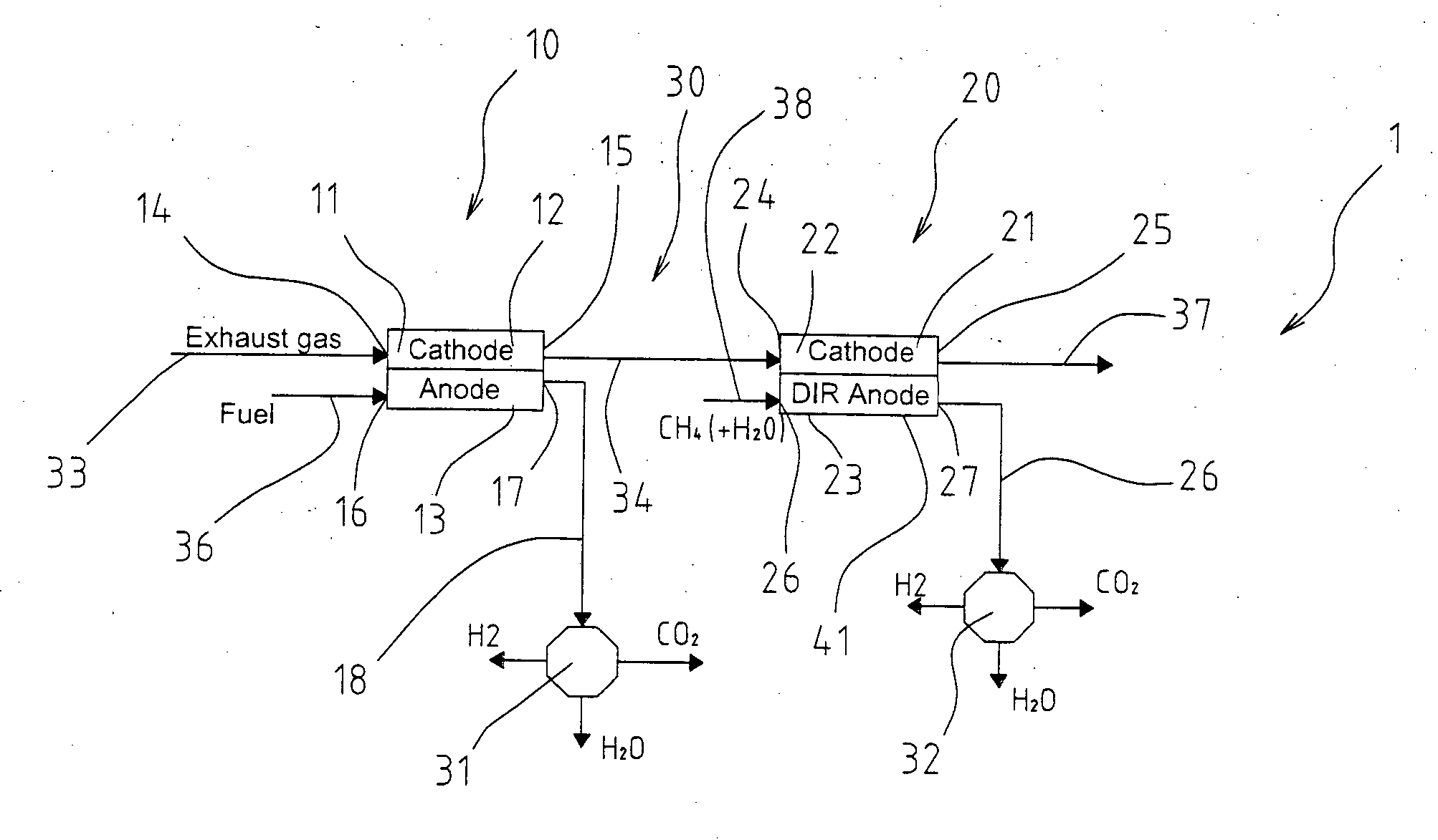
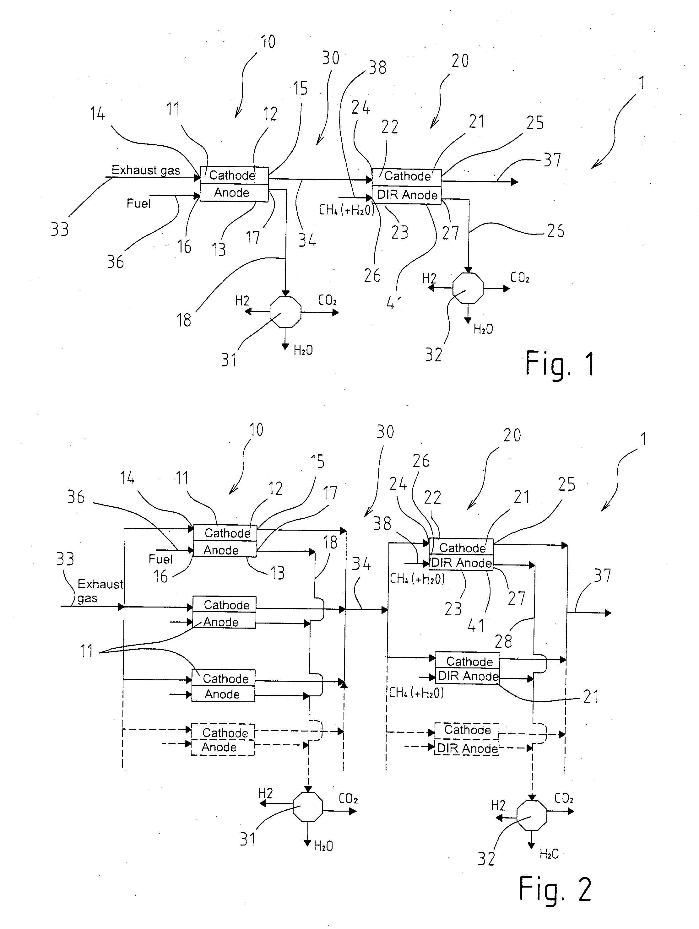
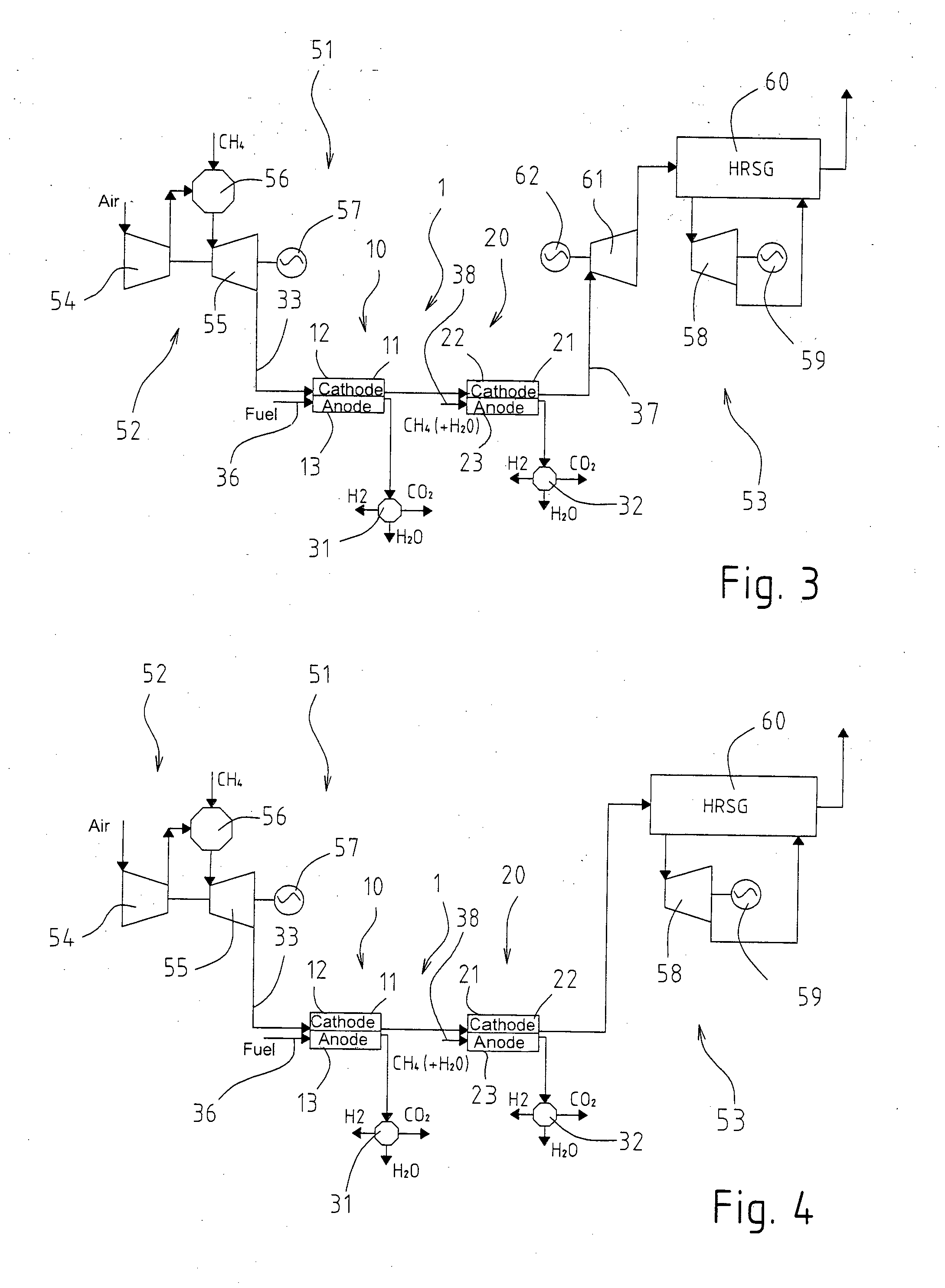
[0048]In FIG. 1 designated as a whole by 1 is a system for the separation of CO2 from combustion exhaust gas, in particular an MCFC-CCS system (i.e., a molten-carbonate fuel-cell system operating as separator of CO2 from combustion exhaust gas).

[0049]The system 1 comprises a first MCFC unit 10, a second MCFC unit 20, and a connection network 30 that connects the units 10, 20 to one another and to at least one, and preferably to respective, CO2-capture units 31, 32.

[0050]Each unit 10, 20 includes at least one MCFC 11, 21 and preferably a stack of MCFCs 11, 21; in any case, the cells 11, 21 of the units 10, 20 have respective cathodic compartments 12, 22 and respective anodic compartments 13, 23.

[0051]The cathodic compartments 12 of the cells 11 of the first unit 10 have a cathodic inlet 14, connected to a exhaust-supply line 33, which supplies the cathodic compartments 12 with an oxidizing gas flow made up, in particular, of combustion exhaust gas coming from an industrial plant that...


PUM

PropertyMeasurementUnit
energyaaaaaaaaaa
thermal managementaaaaaaaaaa
electrical energyaaaaaaaaaa

Abstract

A system for separating CO2 from combustion exhaust gas by means of MCFC multistacks comprises: a first MCFC unit (10) and a second MCFC unit (20), having respective cells (11, 21) with respective cathodic compartments (12, 22) and respective anodic compartments (13, 23); at least one CO2-capture unit (31, 32); and a connection network (30) that connects the units (10, 20) to one another and to the CO2-capture unit (31,32); the first unit (10) is formed by one or more MCFC cells (11) without active direct internal reformer; and the second unit (20) is formed by one or more MCFC cells (21) with active direct internal reformer; the units (10, 20) are connected in such a way that the exhaust gas to be treated are supplied to the cathodic compartments (12) of the cells (11) of the first unit (10), and the cathodic compartments (22) of the cells (21) of the second unit (20) are supplied with cathodic exhaust of the first unit (10), either alone or with additions that do not include portions of exhaust gas that have not previously passed into the cathodic compartments (12) of cells (11) of the first unit (10).

Description

TECHNICAL FIELD[0001]The present invention relates to a system and a method for separating CO2 from combustion exhaust gas by means of molten-carbonate-fuel-cell (MCFC) multistacks.[0002]More precisely, the subject of the invention is an MCFC system, in particular an MCFC multistack system, i.e., a system made up of a number of stacks of MCFCs (or by a number of blocks of stacks), having an internal configuration that enables it to operate as separator of CO2 from combustion exhaust gas (flue gas) generating at the same time electrical energy with high efficiency, simplified water management, and limited requirements of supplementary cleaning of the gas.[0003]The invention hence falls within the field of systems for separation of CO2 from combustion exhaust gas and more specifically within the sector of processes and devices capable of selectively extracting CO2 from the exhaust gas in which it is diluted so as to render it available in concentrated form in a gas flow from which it ...

Claims


Application Information

Patent Timeline
Patent Type & Authority Applications(United States)
IPC IPC(8): H01M8/06F01K23/10
CPCH01M8/0618H01M8/0625H01M8/0637H01M8/0668H01M8/0662H01M8/249Y02E60/526Y02C10/04Y02E20/16H01M8/145Y02E60/50Y02C20/40B01D53/62H01M8/06H01M8/14H01M8/24
Inventor CAPRILE, LUCIANOPASSALACQUA, BIAGIOTORAZZA, ARTURO
Owner ANSALDO ENERGIA SPA
Why Eureka
Try Eureka