Radiation generating apparatus and radiation imaging apparatus using the same

a radiation generation apparatus and radiation imaging technology, applied in the field of radiation imaging apparatus, can solve problems such as lowering the voltage withstanding, and achieve the effects of high stability of the electrostatic performance, high reliability, and high electrostatic performan

Inactive Publication Date: 2013-01-17
CANON KK
View PDF6 Cites 25 Cited by
  • Summary
  • Abstract
  • Description
  • Claims
  • Application Information

AI Technical Summary

Benefits of technology

[0011]The radiation generating apparatus according to the present invention has a structure in which a window provided in the storage container 1 that has the insulating liquid provided in its inside, and an aperture substrate of a tubular shielding member that is provided in the radiation generating tube arranged inside the storage container 1 are arranged so as to oppose to each other, and the end of the tubular shielding member in the substrate aperture 21 side is covered with the solid insulating member. In the radiation generating apparatus, a portion in which the electric filed is particularly concentrated in the end of the tubular shielding member is covered with a solid insulating member having electrostatic performance higher than that of the insulating liquid and having a high stability of the electrostatic performance. Accordingly, a radiation generating apparatus can be provided which suppresses an electric discharge between the radiation generating tube and the storage container 1, and is highly reliable. Furthermore, the radiation generating apparatus can shorten a distance between the radiation generating tube and the storage container, by the enhancement of the electric voltage withstanding, and accordingly can achieve also the reduction of its size and weight.

Problems solved by technology

In such an insulating liquid in the electric-field concentrated environment, such a problem has occasionally occurred that voltage withstanding is lowered as in the case that an electric discharge occurs between the shielding member and the storage container 1 which is set at the ground potential.
However, though Japanese Patent Application Laid-Open No. 2007-80568 discloses the radiation generating apparatus of middle-point grounding, the potential of the radiation emitting port is an approximately ground potential, and such a problem is hard to occur that an electric discharge is generated between the radiation emitting port and a storage container which is set at the same ground potential as that of the radiation emitting port.
Furthermore, Japanese Patent Application Laid-Open No. 2007-80568 does not disclose a special reason why the place of the insulating member to be arranged is selected, and does not give a special suggestion for solving the above described problem.

Method used


Image

  • Radiation generating apparatus and radiation imaging apparatus using the same
  • Radiation generating apparatus and radiation imaging apparatus using the same
  • Radiation generating apparatus and radiation imaging apparatus using the same

Examples


exemplary embodiment 1

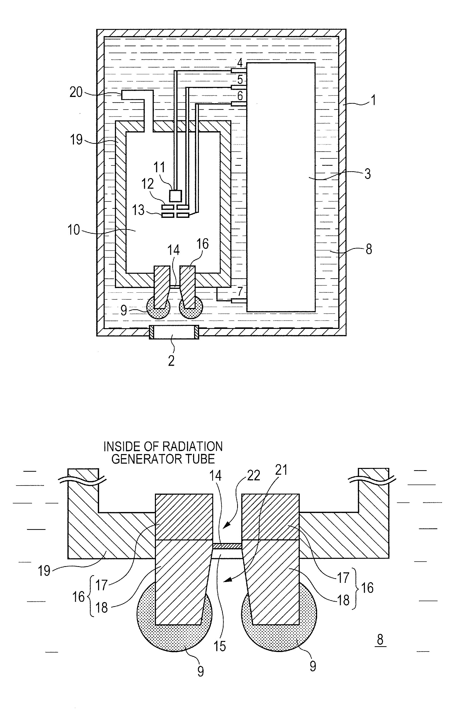
[0047]In Exemplary Embodiment 1, a radiation generating apparatus of FIGS. 1A and 1B was used. Each member and the radiation generating apparatus are as described above, and accordingly the descriptions are omitted.

[0048]In the present exemplary embodiment, an epoxy resin material was selected as a solid insulating member 9, and was fixed on a second shielding member 18 so as to cover the inner side protruding portion and the outer side protruding portion on the end face of the second shielding member 18. The insulating member 9 covered a region surrounded by the inner side protruding portion and the outer side protruding portion on the end face of the second shielding member 18. The thickness of the insulating member 9 on the inner side protruding portion and the outer side protruding portion of the end face of the second shielding member 18 was set in the above described range. An insulating oil formed of a mineral oil was used as an insulating liquid 8. In addition, the middle-po...

exemplary embodiment 2

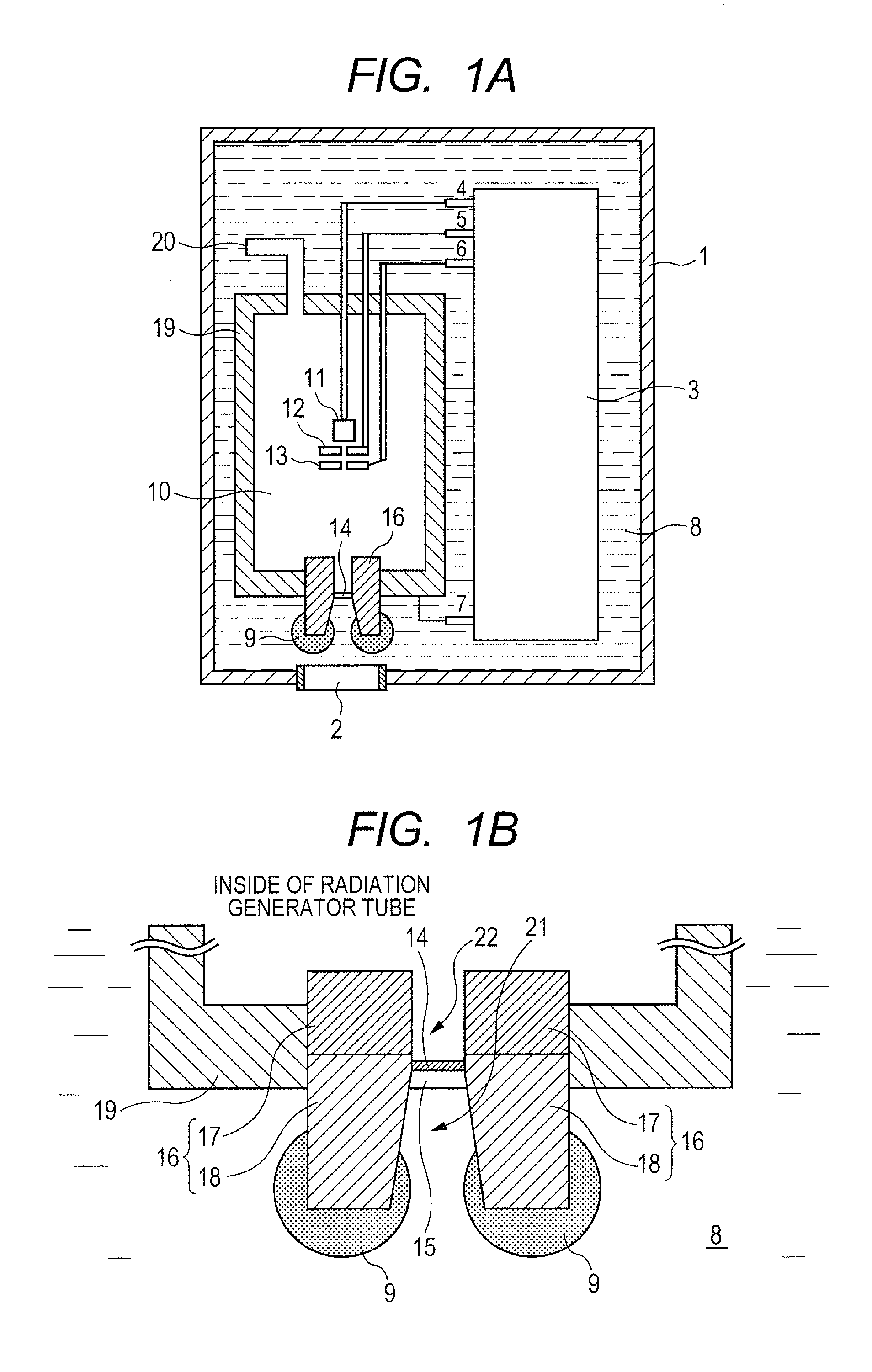
[0057]In Exemplary Embodiment 2, a radiation generating apparatus of FIG. 2 was used. The present exemplary embodiment is different from Exemplary Embodiment 1 in the point that a first insulating member which covers the inner side protruding portion on the end face of the second shielding member 18 and a second insulating member which covers the outer side protruding portion on the end face of the second shielding member 18 are used as a solid insulating member 9. Except this point, the same members and structure of the radiation generating apparatus as in Exemplary Embodiment 1 were used. The thickness of the insulating member 9 on the inner side protruding portion and the outer side protruding portion on the end face of the second shielding member 18 was set in the above described range. The radiation was radiated on similar conditions to those in Exemplary Embodiment 1, while using the radiation generating apparatus of FIG. 2, and the dose of the generated radiation was measured...

exemplary embodiment 3

[0058]In Exemplary Embodiment 3, a radiation generating apparatus of FIG. 3 was used. The present exemplary embodiment is different from Exemplary Embodiment 1 in the point that the whole region surrounded by the outer side protruding portion on the end face of the second shielding member 18 is covered with the solid insulating member 9. Except this point, the same members and structure of the radiation generating apparatus as in Exemplary Embodiment 1 were used. The thickness of the insulating member 9 on the inner side protruding portion and the outer side protruding portion on the end face of the second shielding member 18 was set in the above described range. The radiation was radiated on similar conditions to those in Exemplary Embodiment 1, while using the radiation generating apparatus of FIG. 3, and the dose of the generated radiation was measured. As a result, it was confirmed that a stable dose of the radiation was obtained. In addition, there was no problem in the electri...


PUM


Abstract

A radiation generating apparatus 30 according to the present invention including: a radiation generating tube 10 having a target 14, a tubular shielding member 18 that shields a part of a radiation generated from the target 14 and also has an aperture 21 through which the radiation generated from the target 14 passes, and an envelope 1 that has the target 14 so as to be brought into contact with the internal space thereof and also has the tubular shielding member 18 so as to protrude toward an external space thereof; a storage container 1 for storing the radiation generating tube 3 therein; and an insulating liquid 8 that comes in contact with the tubular shielding member 18 and the storage container 1, wherein the tubular shielding member 18 has a protruding portion P, and the protruding portion P is covered with a solid insulating member 9.

Description

BACKGROUND OF THE INVENTION [0001]1. Field of the Invention[0002]The present invention relates to a radiation generating apparatus which can be applied to non-destructive X-ray imaging or the like in a medical equipment field and an industrial equipment field, and to a radiation imaging apparatus using the same.[0003]2. Description of the Related Art[0004]Generally, a radiation generating tube accelerates electrons to be emitted from an electron emitting source by high voltage, and makes the accelerated electrons irradiate a target including a metal such as tungsten to make the target generate radiation such as X-rays. The radiation which has been generated at this time is emitted toward all directions. Japanese Patent Application Laid-Open No. 2007-265981 discloses a transmission-type radiation generating tube which has a shielding member arranged in an electron-incident side and a radiation-emitting side of the target, so as to shield radiation that heads toward directions other t...

Claims


Application Information

Patent Timeline
Patent Type & Authority Applications(United States)
IPC IPC(8): H01J35/16H01J35/18
CPCH01J35/16H01J35/18G21K1/02H01J2235/168H01J35/14H05G1/06H01J2235/087H01J35/08H01J35/116
Inventor YANAGISAWA, YOSHIHIROUEDA, KAZUYUKITAMURA, MIKIAOKI, SHUJI
Owner CANON KK
Why Eureka
Try Eureka