Laser array mux assembly with external reflector for providing a selected wavelength or multiplexed wavelengths

a technology of laser array and reflector, which is applied in the field of wavelength division multiplexed optical systems, networks, etc., can solve the problems of inefficient tdm approach, complex and expensive cost of deploying and managing many fibers, and increasing the number of fibers

a technology of laser array and reflector, which is applied in the field of wavelength division multiplexed optical systems, networks, etc., can solve the problems of inefficient tdm approach, complex and expensive cost of deploying and managing many fibers, and increasing the number of fibers

US20130016977A1Active Publication Date: 2013-01-17APPLIED OPTOELECTRONICS

Image

  • Laser array mux assembly with external reflector for providing a selected wavelength or multiplexed wavelengths
  • Laser array mux assembly with external reflector for providing a selected wavelength or multiplexed wavelengths
  • Laser array mux assembly with external reflector for providing a selected wavelength or multiplexed wavelengths

Examples


Embodiment Construction

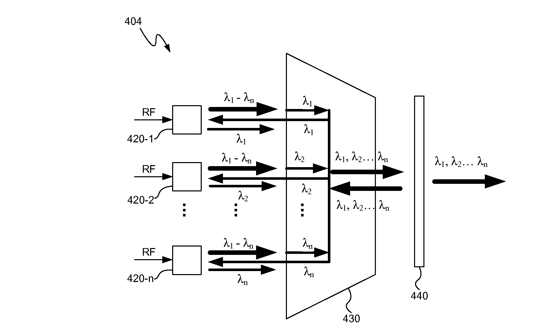
[0020]A laser array mux assembly, consistent with embodiments described herein, generally includes an array of laser emitters coupled to an optical multiplexer, such as an arrayed waveguide grating (AWG), with an external partial reflector after the optical multiplexer. Each of the laser emitters may include a gain region that emits light across a plurality of wavelengths including, for example, channel wavelengths in an optical communication system. The AWG or optical multiplexer filters the emitted light from each of the laser emitters at different channel wavelengths associated with each of the laser emitters. The external partial reflector reflects at least a portion of the filtered light such that lasing occurs at the channel wavelength(s) of the reflected, filtered light. The laser array mux assembly may be used, for example, in a tunable transmitter, to generate an optical signal at a selected channel wavelength. The laser array mux assembly may also be used in a multiplexing...


PUM


Abstract

A laser array mux assembly generally includes an array of laser emitters coupled to an optical multiplexer, such as an arrayed waveguide grating (AWG), with an external partial reflector after the multiplexer. Each of the laser emitters may include a gain region that emits light across a range of wavelengths including, for example, channel wavelengths in an optical communication system. The AWG filters the emitted light from each of the laser emitters at different channel wavelengths associated with each of the laser emitters. The reflector reflects at least a portion of the filtered light such that lasing occurs at the channel wavelengths of the reflected light. The laser array mux assembly may be used to generate an optical signal at a selected channel wavelength or to generate and combine optical signals at multiple channel wavelengths.

Description

CROSS-REFERENCE TO RELATED APPLICATIONS[0001]The present application claims the benefit of U.S. Provisional Patent Application Ser. No. 61 / 508,017 filed on Jul. 14, 2011 (Attorney Docket No. PAT147P), which is fully incorporated herein by reference.TECHNICAL FIELD[0002]The present disclosure relates to wavelength division multiplexed (WDM) optical systems, networks, and methods and more particularly, to a laser array mux assembly with an external reflector for providing a selected wavelength or multiplexed wavelengths.BACKGROUND INFORMATION[0003]Optical communications networks have been deployed for many years. Originally, these networks were generally “point to point” type networks including a transmitter and a receiver connected by an optical fiber. Such networks are relatively easy to construct but deploy many fibers to connect multiple users. As the number of subscribers connected to the network increases, the fiber count also increases rapidly and the expense of deploying and m...

Claims


Application Information

Patent Timeline
17 Jan 2013
Publication
US20130016977A1
IPC
H04J14/02
CPC
H01S5/0268; H01S5/1028; H01S5/4087; H01S5/4062; H01S5/146; H01S5/141; H04J14/0282; H04B10/2587
Inventors
ZHENG, JUN; MURRY, STEFAN J.