
Status control for electrically powered surgical tool systems

a technology of electrically powered surgical tools and status control, applied in the field of medical devices, can solve the problems of increasing biohazardous waste in the environment, high cost of medical waste disposal, and high cost of use, and achieve the effect of accurate and reliable information on efficiency and cost-effectiveness

Inactive Publication Date: 2013-01-17
MEDICAL VISION RES & DEV AB
View PDF0 Cites 845 Cited by
  • Summary
  • Abstract
  • Description
  • Claims
  • Application Information

AI Technical Summary

Benefits of technology

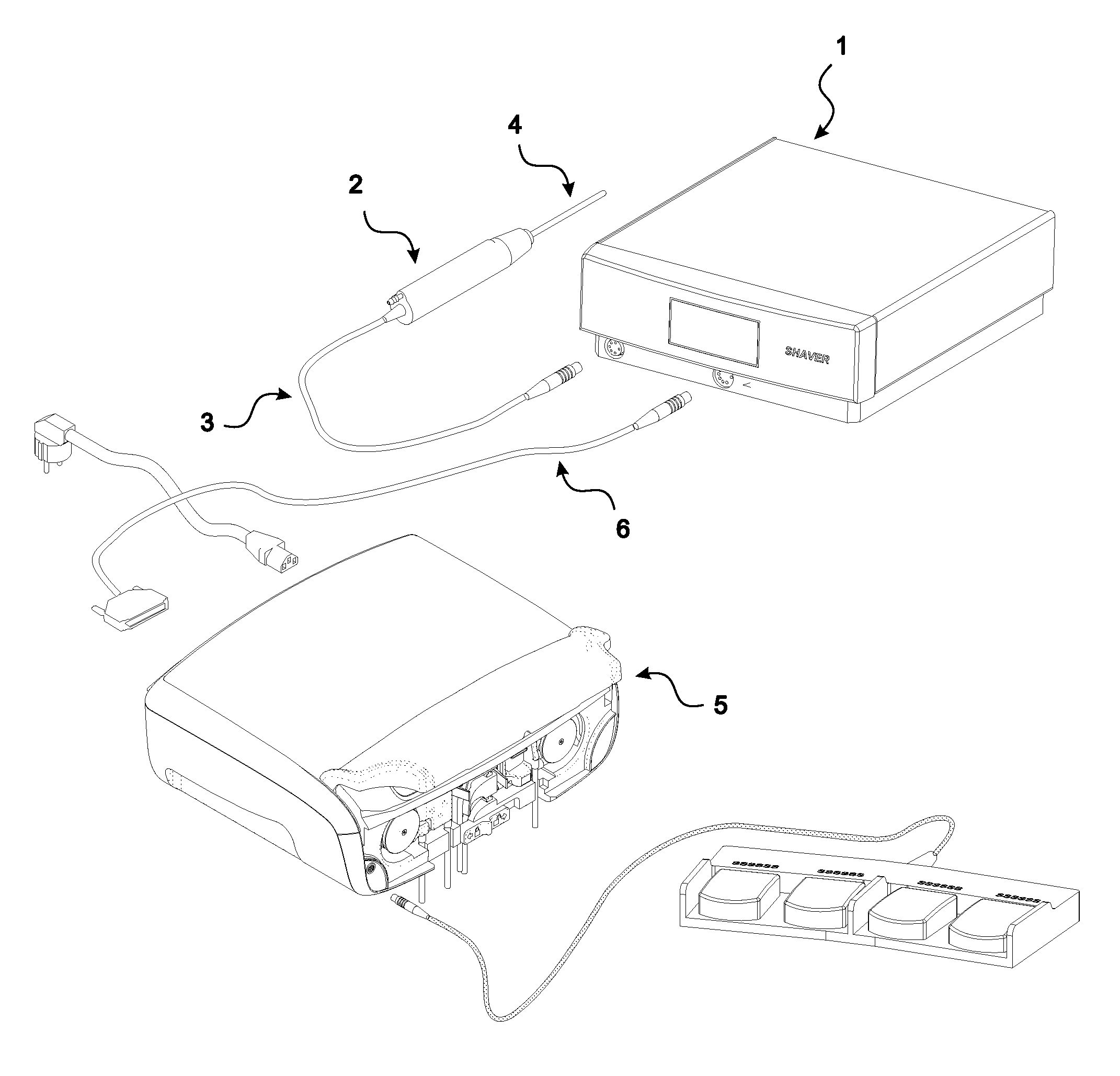
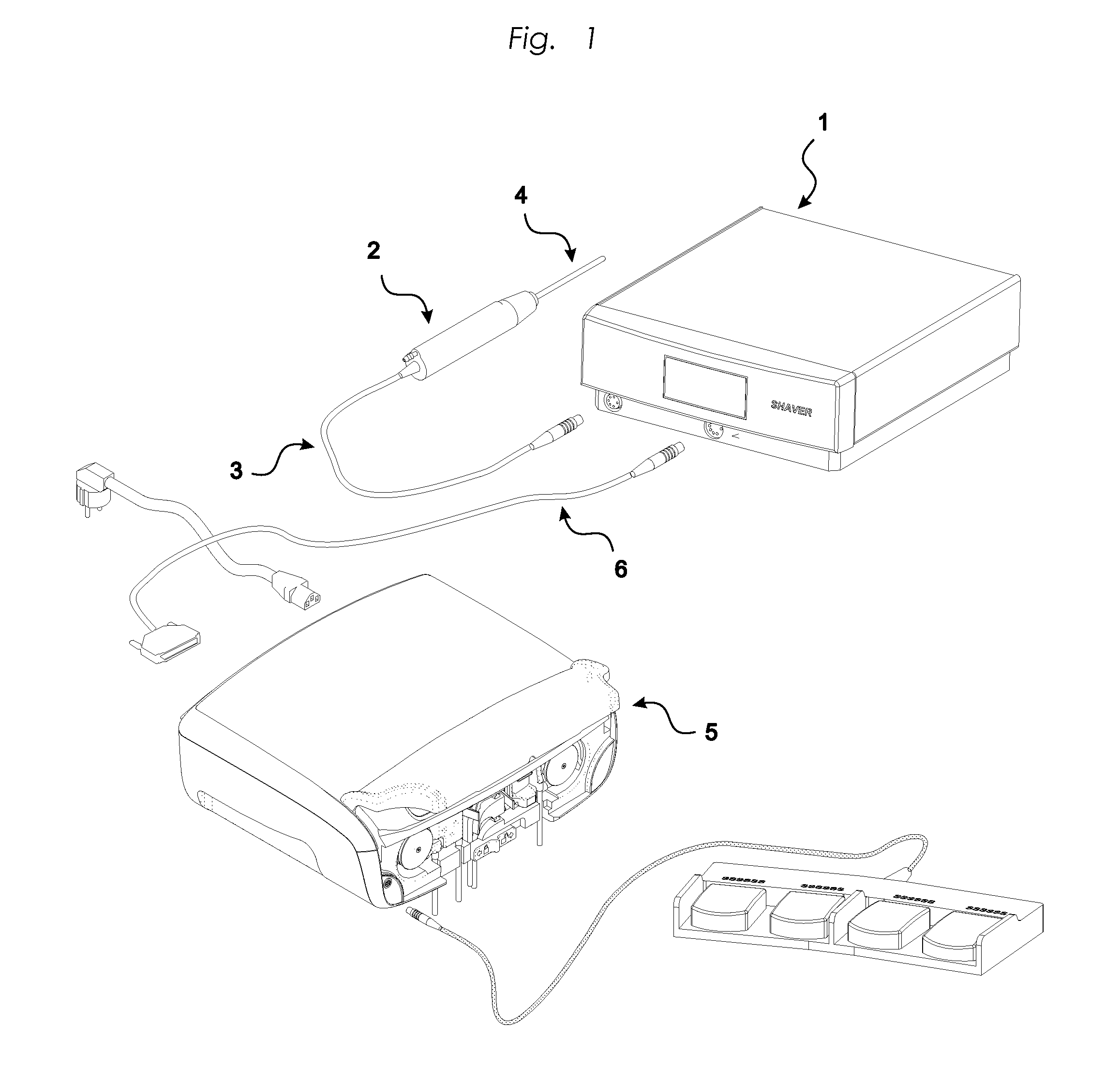
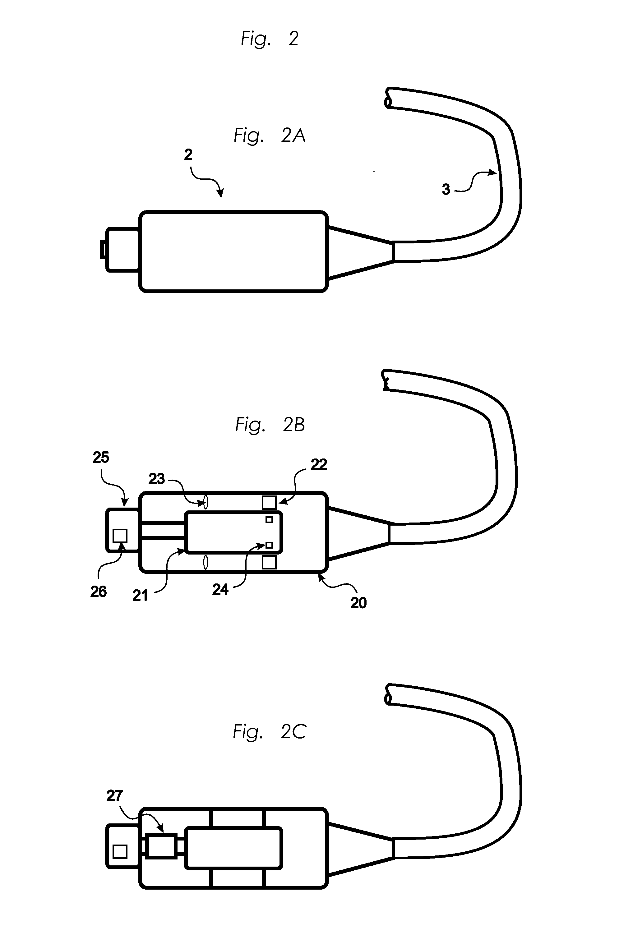
The invention is a system that tracks and records information about a specific surgical device, specifically the cutting accessory used with a powered shaver. The system measures factors that affect the device's deterioration, such as the motor's torque and the number of sterilizations, and logs this information with each use. This helps provide accurate and reliable information on the efficiency and wear of the device, which is important for patient safety and legal compliance. It also enables cost-effective use of the cutting accessory throughout its life cycle.

Problems solved by technology

The main advantage of said powered surgical tools is their ability to accomplish multiple functions, such as bone removal, and suction with one tool, whereas, their primary drawbacks continue to be the high costs associated with their use.
The high cost of disposing of medical waste, increasing biohazardous waste in the environment and burgeoning healthcare costs are the reasons behind the increased demand of reusable devices and devices with extended lifetime.
However, over time and through ordinary usage, reusable surgical instruments suffer wear or damage and eventually reach the end of their life cycle.
These systems neither disclose nor address the problem related to the wear of the reusable accessory.
In general, the problem of the current systems for reusable shavers are related to the fact that the number of times a cutting accessory e.g. a shaver blade, has been used, measured by the number of times it has been fitted to the handpiece, the power consumed or the number of times it has been sterilized does not well enough reflect the wear of the specific blade i.e. when it has to be replaced.
It may have been used in several very short procedures, or in a surgical operation with several high torque peaks, or on demanding tissue, which means very different wear and need for replacement.
Furthermore, those systems relying on the information at which the cutting device operates optimally are only aimed at minimizing wear, and as such, do not address the problem of measuring and informing about the device's actual wear.

Method used


Image

  • Status control for electrically powered surgical tool systems
  • Status control for electrically powered surgical tool systems
  • Status control for electrically powered surgical tool systems

Examples


example 1

Calculation of Utilization Level Considering Different Variable Factors

[0045]The invention herein teaches an algorithm for accurately calculating the level of utilization or wear, UL. Different factors such as the sensitivity to torque, k, of each accessory, will add further accuracy to our method. The value of k differs for each type of cutting tool ((burr, aggressive burrs, meniscus cutters).

[0046]UF 1 is the first Utilization Factor, wherein:

UF 1=begin∫endk1×m×r(dt).

k1 is the sensitivity to torque

begin∫end is the integral of the time the cutting accessory starts and ends rotation

m is the torque [Nm]

r is rotation speed [rpm]

dt is the accessory running time in the specific interval

[0047]The value of k1 is directly proportional to wear. A high constant value for a specific type of cutting tool will mean rapid wear at a certain torque speed.

[0048]Each time interval, and hence each Utilization Level, UL, will consider several UF values e.g. UF1, UF2, UF3 and UF4, which are sensible or...

example 2

[0060]The general methodology described in Example 1 is hereby employed for calculating the Utilization Level when using a “meniscus cutter” during two operational procedures. This tool has a steel quality of DIN 1.4305, a material well suitable for the purpose. The specific material and product type determine the value of each parameter in the Utilization Level algorithm:

k1′=0.0001

k2=0.00001

y=3.0

k3=0.000002

k4=2

[0061]The initial run time (dt1) of the meniscus cutter is in this example 20 seconds with a moderate low average torque (m) of 0.06 Nm, representing soft tissue. Thereafter a second run (dt2) of only one second has a high torque of 5 Nm, as the tool is pressed hard against bone material. The rotation speed is 4 000 rpm.

[0062]For the first 20 second run:

UF1=0.0001×0.06×4 000×20=0.48

UF2=0.00001(×(1+0.06)3.0×4 000×20=0.95

UF3=0.000002×4 000×20=0.16

UF4=2

[0063]The Utilization Level that applies to this 20 second run is calculated as follow:

UL=0.48+0.95+0.16+2=3.59%

[0064]In the sec...

example 3

Wear Calculations Using Max Torque as the Only Variable Factor

[0067]As depicted in FIG. 5, the various levels of torque can in an alternative calculation method to the above be classified into different torque categories. In this example, if the torque is in the range 0-0.7 Nm it falls into category A, if it is from 0.7 to 2 Nm it falls into category B; and if over 2 Nm it falls into category C. A surgical procedure in which the torque is in category A during the whole process, will have an Utilization factor UFA that is the result of multiplying the time the torque falls within this category by 1.

[0068]For category B and C the Utilization Factor is obtained by multiplying the torque by 1.5 and 5, respectively. The torque falls under category A in those cases when the cutting accessory is used for cutting soft tissue; in category B for hard tissue; and in category C for cutting bone material. The time each torque category has occurred adds to the representative Utilization factor A,...


PUM


Abstract

The present invention relates to a method for determining a utilization level (UL; ULtot) indicating a degree of utilization of a re-usable cutting accessory (4) for endoscopic surgery, such as an arthroscopic shaver blade, removably connectable to a handpiece (2) comprising a motor (21) driving the cutting accessory (4) during surgical procedures. The method provides a reliable measure of the utilization level of the cutting accessory (4) by determining the utilization level (UL) of the cutting accessory (4) through calculation of at least one utilization factor (UF1, UF2) that is calculated based on a torque (40) measured when said cutting accessory (4) is driven by said motor (21).

Description

RELATED APPLICATIONS[0001]This application is claiming priority to U.S. Application No. 61 / 572,096 filed on Jul. 11, 2011 and is incorporated herein by reference in its entirety.BACKGROUND OF THE INVENTION[0002]1. Technical Field[0003]The present invention relates to medical devices used in surgery including arthroscopic shavers with integrated identification and status control systems.[0004]2. Description of the Related Art[0005]Endoscopic surgery is performed within the natural cavities of the human body. A small hole is created in the skin of the patient and an optical instrument, the endoscope, is positioned in the cavity. The endoscope can consist of a rigid flexible tube having channels for light, fluid etc., depending on the endoscopy application. Specific applications of this procedure include: Laparoscopy, enteroscopy, colonoscopy, sigmoidoscopy, proctoscopy, cystoscopy, arthroscopy, etc.[0006]The ability to perform endoscopic surgery is enhanced by the development of power...

Claims


Application Information

Patent Timeline
Patent Type & Authority Applications(United States)
IPC IPC(8): A61B17/32
CPCA61B17/32002A61B19/46A61B2019/301A61B2019/448A61B2019/4815A61B2019/4836A61B2019/4873A61B2019/466A61B90/06A61B90/98A61B2090/031A61B2090/066A61B2090/0803A61B2090/0807A61B2090/0814
Inventor MILTON, SVENMOLLSTAM, ANDERS
Owner MEDICAL VISION RES & DEV AB
Learn More