Rapid manufacturing of porous metal prostheses

a technology of porous metal and prosthesis, which is applied in the field of porous metal prosthesis manufacturing, can solve the problems of high temperature, a significant amount of time, and the need for orthopaedic prosthesis manufacturing to be completed

Active Publication Date: 2013-01-17
ZIMMER INC
View PDF2 Cites 132 Cited by
  • Summary
  • Abstract
  • Description
  • Claims
  • Application Information

AI Technical Summary

Benefits of technology

[0006]The present disclosure provides an orthopaedic prosthesis having a solid bearing layer, a porous bone-ingrowth layer, and an interdigitating layer therebetween. The present disclosure also provides a method for rapidly manufacturing the orthopaedic prosthesis, such as by performing a laser sintering process.
[0007]According to an embodiment of the present disclosure, a method is provided for rapidly manufacturing an orthopaedic prosthesis. The orthopaedic prosthesis has a porous substrate, the porous substrate including an outer surface and a plurality of ligaments that define pores beneath the outer surface. The method includes the steps of: depositing a plurality of metal powder particles onto the outer surface of the porous substrate; allowing at least a first portion of the plurality of metal powder particles to enter the pores beneath the outer surface of the porous substrate, the first portion of the plurality of metal powder particles being sized to fit within the pores of the porous substrate; and applying an energy source to the first portion of the plurality of metal powder particles to form solid metal, the solid metal interdigitating into the pores of the porous substrate.
[0008]According to another embodiment of the present disclosure, a method is provided for rapidly manufacturing an orthopaedic prosthesis. The orthopaedic prosthesis has a solid metal component and a porous metal component, the porous metal component including a plurality of ligaments that define pores. The method includes the steps of: depositing a plurality of metal powder particles into the pores of the porous metal component; and directing an energy source into the pores of the porous metal component to convert the plurality of metal powder particles in the pores to solid metal in the pores, the solid metal in the pores coupling the solid metal component to the porous metal component.

Problems solved by technology

Diffusion bonding, however, requires a significant amount of time to complete and subjects the orthopaedic prosthesis to high temperatures.

Method used


Image

  • Rapid manufacturing of porous metal prostheses
  • Rapid manufacturing of porous metal prostheses
  • Rapid manufacturing of porous metal prostheses

Examples


Embodiment Construction

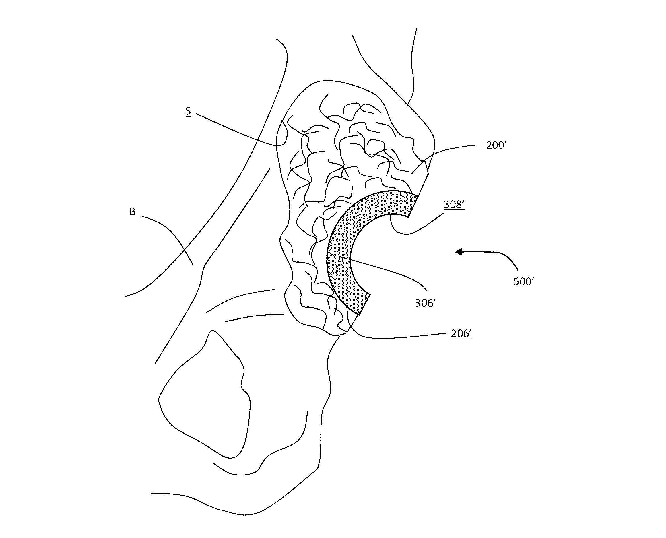
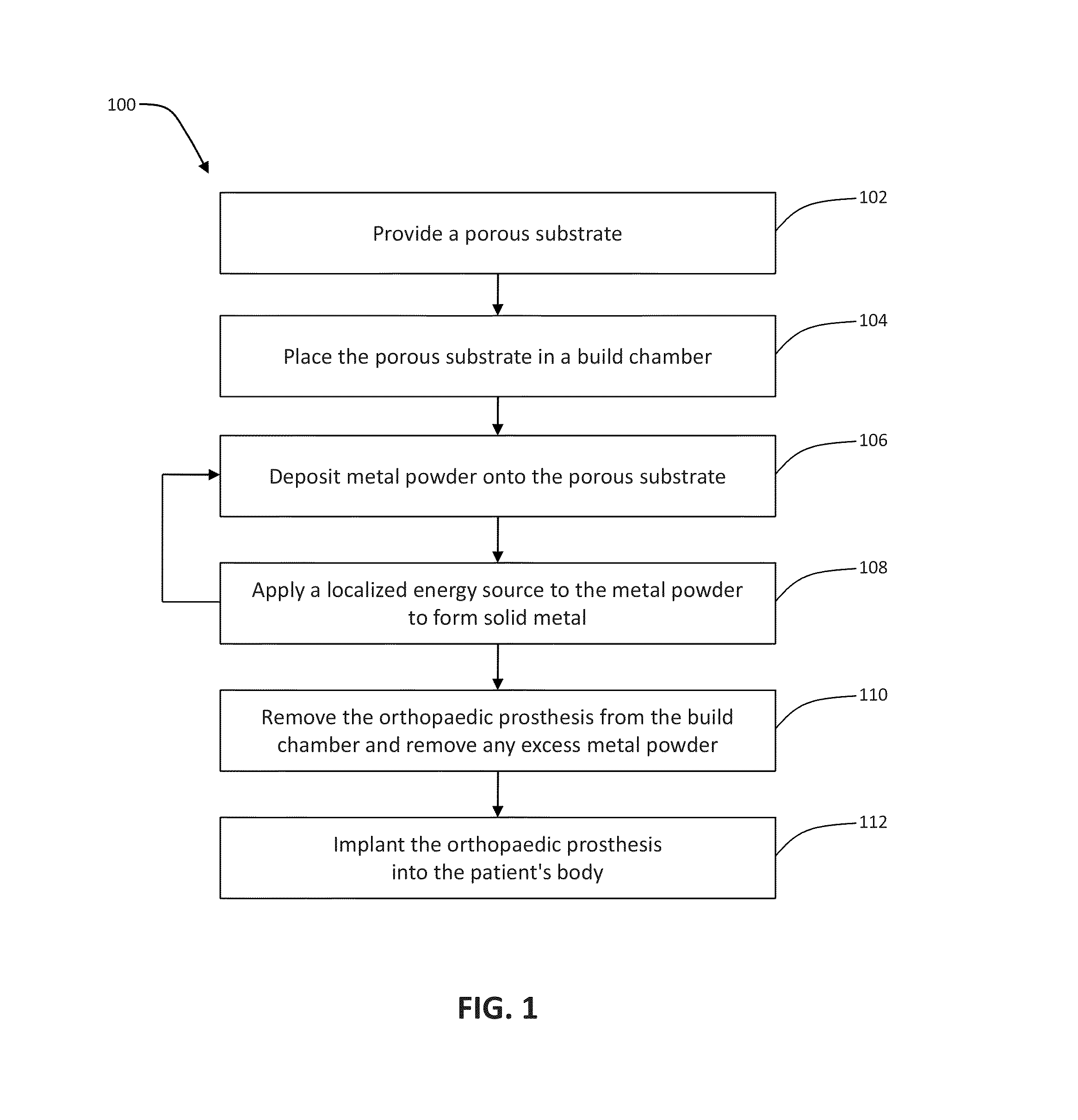
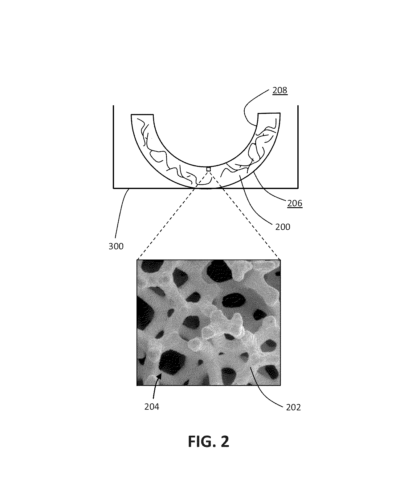
[0023]FIG. 1 provides an exemplary method 100 for designing and manufacturing an orthopaedic prosthesis. Method 100 is exemplified with reference to FIGS. 2-7.

[0024]Beginning at step 102 of method 100 (FIG. 1), a porous substrate 200 is provided having a large plurality of struts or ligaments 202 that define open spaces or pores 204 therebetween, as shown in FIG. 2. Ligaments 202 may be constructed, at least in part, of a first biocompatible metal, such as tantalum, a tantalum alloy, niobium, a niobium alloy, or another suitable metal, for example. In an exemplary porous substrate 200, pores 204 between ligaments 202 form a matrix of continuous channels having no dead ends, such that growth of cancellous bone and / or soft tissue through porous substrate 200 is uninhibited. Thus, porous substrate 200 may provide a matrix into which cancellous bone and / or soft tissue may grow to provide fixation of porous substrate 200 to the patient's bone.

[0025]According to an exemplary embodiment of...


PUM

PropertyMeasurementUnit
sizeaaaaaaaaaa
sizeaaaaaaaaaa
thicknessaaaaaaaaaa

Abstract

An orthopaedic prosthesis and a method for rapidly manufacturing the same are provided. The orthopaedic prosthesis includes a solid bearing layer, a porous bone-ingrowth layer, and an interdigitating layer therebetween. A laser sintering technique is performed to manufacture the orthopaedic prosthesis.

Description

CROSS REFERENCE TO RELATED APPLICATION[0001]This application claims priority from U.S. Provisional Patent Application Ser. No. 61 / 507,151, filed Jul. 13, 2011, the disclosure of which is hereby expressly incorporated by reference herein in its entirety.FIELD OF THE DISCLOSURE[0002]The present disclosure relates to porous metal prostheses. More particularly, the present disclosure relates to rapid manufacturing of porous metal prostheses.BACKGROUND OF THE DISCLOSURE[0003]Orthopaedic prostheses are commonly used to replace at least a portion of a patient's bone following traumatic injury or deterioration due to aging, illness, or disease, for example.[0004]When the orthopaedic prosthesis is implanted into a joint, the orthopaedic prosthesis may be configured to articulate with an adjacent orthopaedic component. For example, when the orthopaedic prosthesis is implanted into the patient's hip joint, the orthopaedic prosthesis may be socket-shaped to receive and articulate with an adjace...

Claims


Application Information

Patent Timeline
Patent Type & Authority Applications(United States)
IPC IPC(8): A61F2/28B05D3/06
CPCA61L27/04B22F3/11A61L27/56B33Y80/00Y02P10/25B22F3/105A61F2/28B05D1/12B05D3/0254B05D5/00
Inventor LI, JIAGRINER, ADAM M.
Owner ZIMMER INC
Why Eureka
Try Eureka