Seat heater and capacitive occupancy sensor combination

a capacitive measurement circuit and seat heater technology, applied in the direction of pedestrian/occupant safety arrangements, transportation and packaging, etc., can solve the problems of large cores of inductor wound on the inductor, the device may not operate in sensing mode and heating mode, and the capacitive measurement circuit and seat heater at the same time. , to achieve the effect of improving detection performance and cost-efficient manufactur

Active Publication Date: 2013-01-24
IEE INT ELECTRONICS & ENG SA
View PDF7 Cites 26 Cited by
  • Summary
  • Abstract
  • Description
  • Claims
  • Application Information

AI Technical Summary

Benefits of technology

[0011]The present invention provides a combined seat heater and capacitive occupancy sensor having the potential of more cost-efficient manufacture and improved detection performance.

Problems solved by technology

The device may not operate in sensing mode and in heating mode at a time.
A disadvantage of the system disclosed in U.S. Pat. No. 6,703,845 is that the inductors used as AC-decoupling elements have to support the full heating current (up to 10 A DC and more) and present high AC impedance to the capacitive measurement circuit and the seat heater at the same time.
High inductance and high operating DC current implies that the inductor have to be wound on large cores, which are expensive.

Method used


Image

  • Seat heater and capacitive occupancy sensor combination
  • Seat heater and capacitive occupancy sensor combination
  • Seat heater and capacitive occupancy sensor combination

Examples


first embodiment

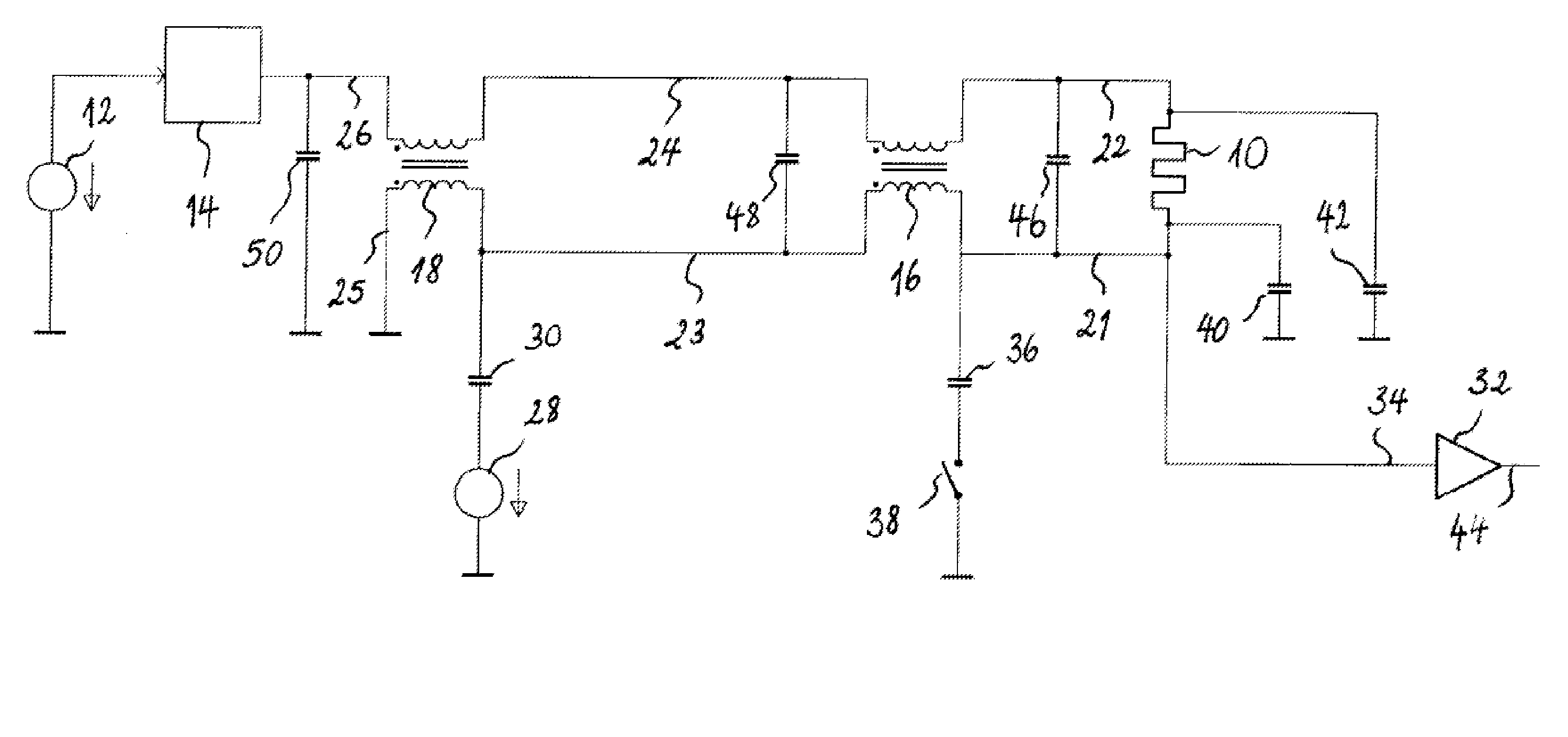
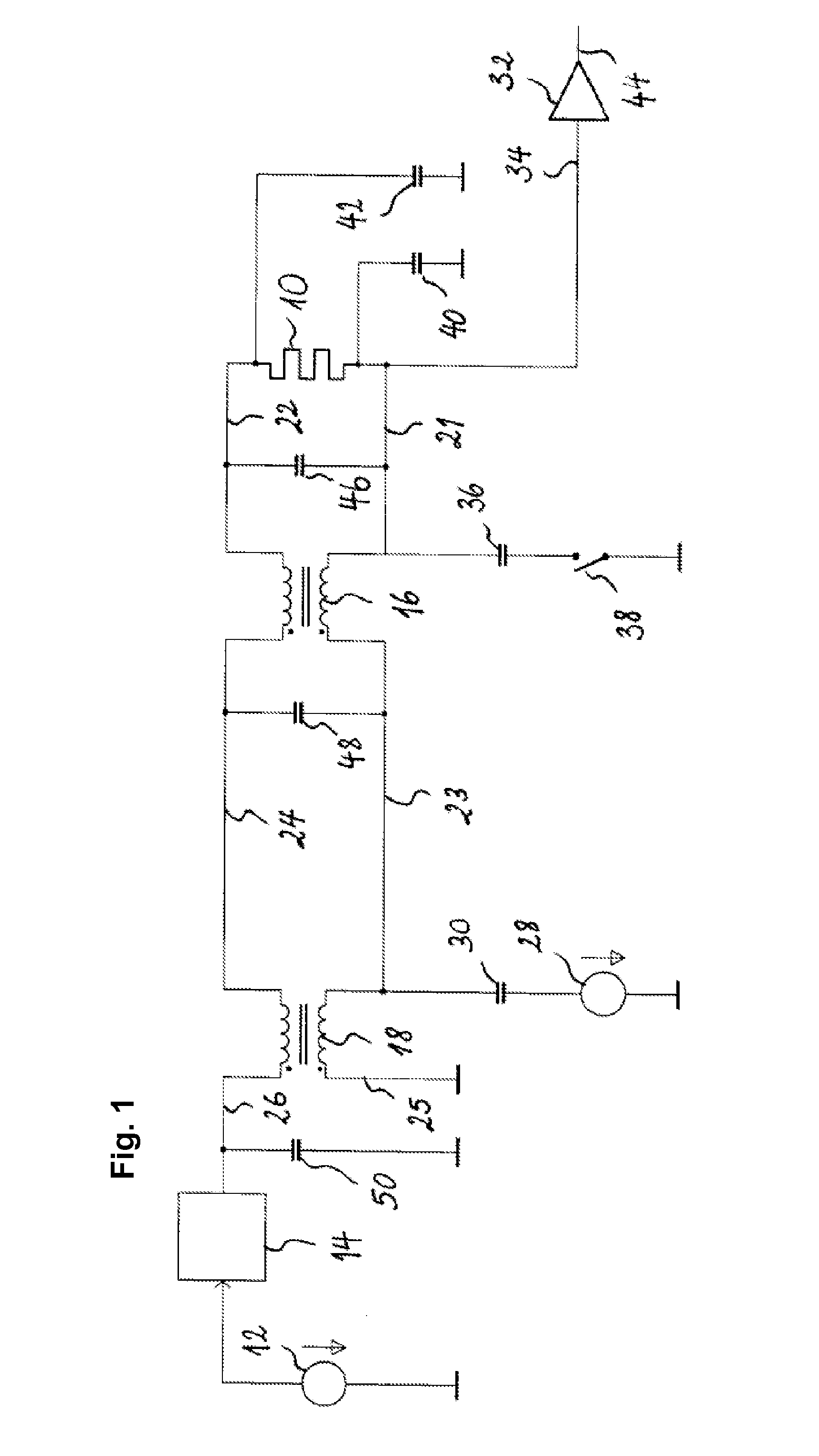
[0036]FIG. 1 shows a block schematic diagram of a combined seat heater and capacitive occupancy sensor according to the invention. The seat heater comprises a heating element 10, which is used by the capacitive occupancy sensor as an antenna electrode, which capacitively couples to ground. The strength of the capacitive coupling between the heating element 10 and ground depends on whether an occupant is present in the zone between the heating element 10 and the grounded counter-electrode. In a loading-mode capacitive occupancy sensor for a vehicle seat, the grounded counter-electrode normally corresponds to the vehicle chassis.

[0037]Turning first to the seat heater, the heater network includes power source 12 supplying the required DC heating current to the heating element 10 to perform the heating function. The heater network comprises a switch 14, which turns the DC heating current on and off, depending on the actual and required temperature of the seat heater. The switch 14 may e...

second embodiment

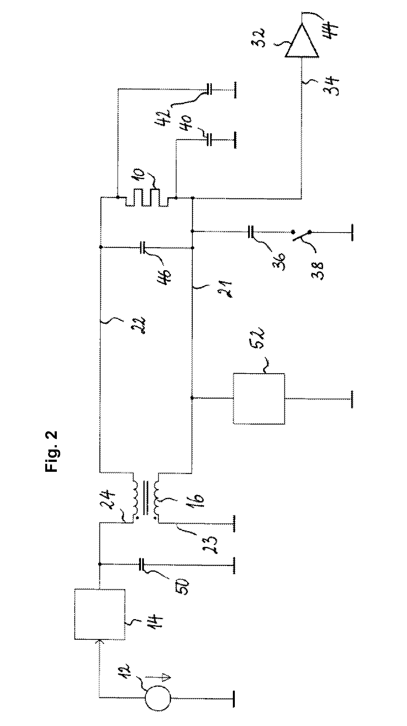
[0053]FIG. 2 shows a block schematic diagram of a combined seat heater and capacitive occupancy sensor according to the invention. Elements common to the embodiments of FIG. 1 and FIG. 2, having the same or substantially the same function, have been given the same reference numbers in FIG. 2. As in the previously described embodiment, the seat heater comprises a heating element 10, which is used by the capacitive occupancy sensor as an antenna electrode, which capacitively couples to ground. The capacitance to be measured by the capacitive sensing network is again symbolically represented as capacitors 40 and 42.

[0054]In the heater network of the embodiment of FIG. 2, the heating element 10 is connected between a first 21 and a second 22 node. The heating element 10 is operatively connected to the power source 12 with a common mode choke 16 that connects the first 21 and the second 22 node to a third 23 and a fourth 24 node, respectively. In FIG. 2, the third node 23 corresponds to ...

third embodiment

[0072]FIG. 5 shows a block schematic diagram of a combined seat heater and capacitive occupancy sensor according to the invention. Elements common to the embodiments of FIG. 2 and FIG. 5, having the same or substantially the same function, have been given the same reference numbers in FIG. 5. As in the previously described embodiments, the seat heater comprises a heating element 10, which is used by the capacitive occupancy sensor as an antenna electrode, which capacitively couples to ground. The capacitance to be measured by the capacitive sensing network is again symbolically represented as capacitors 40 and 42. In the figures described in the following, the reference capacitor and its switch are not shown. Those skilled will appreciate, however, that such reference capacitor or other reference component could be used in the same manner as discussed with respect to FIG. 2.

[0073]In the embodiment of FIG. 5, an AC source 74 supplying an AC current into the resonant network, operatin...


PUM


Abstract

A combined seat heater and capacitive occupancy sensor comprises a heater network and a capacitive sensing network. The heater network includes a heating element (10) connected between a first node (21) and a second node (22) to dissipate heat. The capacitive sensing network is connected to the heating element to apply an oscillating current thereto and to derive a capacitive load of the heating element from the voltage resulting on the heating element. The heater network comprises a common mode choke (16) connecting the first and the second node to a third (23) and a fourth (24) node, respectively. The capacitive sensing network further comprises means to sustain the oscillating current in or to drive the oscillating current into the heating element as well as a high-impedance amplifier (32) having an input node operatively connected to the heating element to probe the resulting voltage, and an output node (44) to provide an output signal indicative of the voltage.

Description

FIELD OF THE INVENTION[0001]The present invention generally relates to a capacitive occupant detection system, e.g. for detecting the absence or presence of an occupant seated on a vehicle seat. More specifically, the invention relates to a combined seat heating and capacitively occupancy-sensing device.BACKGROUND OF THE INVENTION[0002]A capacitive sensor, called by some electric field sensor or proximity sensor, designates a sensor, which generates a signal responsive to the influence of what is being sensed (a person, a part of a person's body, a pet, an object, etc.) upon an electric field. A capacitive sensor generally comprises at least one antenna electrode, to which is applied an oscillating electric signal and which thereupon emits an electric field into a region of space proximate to the antenna electrode, while the sensor is operating. The sensor comprises at least one sensing electrode at which the influence of an object or living being on the electric field is detected. ...

Claims


Application Information

Patent Timeline
Patent Type & Authority Applications(United States)
IPC IPC(8): H05B1/00
CPCB60N2/002B60R21/01532B60N2/5685
Inventor LAMESCH, LAURENTVIRNICH, MICHAELSCHOOS, ALOYSE
Owner IEE INT ELECTRONICS & ENG SA
Why Eureka
Try Eureka