Supercharge Your Innovation With Domain-Expert AI Agents!

Exposure apparatus and device manufacturing method

a technology of exposure apparatus and manufacturing method, which is applied in the direction of photomechanical treatment, printing, instruments, etc., can solve the problems of reducing the measurement accuracy of alignment measurement system, directly affecting imaging performance, and breaking of anti-adhesion film, etc., and achieves the effect of suppressing the effects of heat and vibration

Active Publication Date: 2013-01-24
CANON KK
View PDF5 Cites 12 Cited by
  • Summary
  • Abstract
  • Description
  • Claims
  • Application Information

AI Technical Summary

Benefits of technology

The present invention is an exposure apparatus that can protect an original from heat and vibration. The technical effect of this invention is that it can prevent damages to originals during the exposure process.

Problems solved by technology

Consequently, the gas may reduce the measurement accuracy of an alignment measurement system for performing the positioning of the original or may generate fluctuations in light directed from the original toward the projection optical system.
In addition, thermal deformation of the original itself may also directly affect imaging performance.
Fluid vibration or pressure fluctuation caused by non-uniformity between the supply amount and the recovery amount of the temperature control fluid adversely affects an original, resulting in possible breakage of an anti-adhesion film.
Furthermore, from the viewpoint of the piping implementation, the laying of the piping near the original stage becomes complicated, resulting in an increase in a mechanical load on the original stage.
If such a configuration is applied, the piping must be detached during the exchange of the original, not only resulting in a redundancy of an original conveyance mechanism but also causing the occurrence of particles.

Method used


Image

  • Exposure apparatus and device manufacturing method
  • Exposure apparatus and device manufacturing method
  • Exposure apparatus and device manufacturing method

Examples


first embodiment

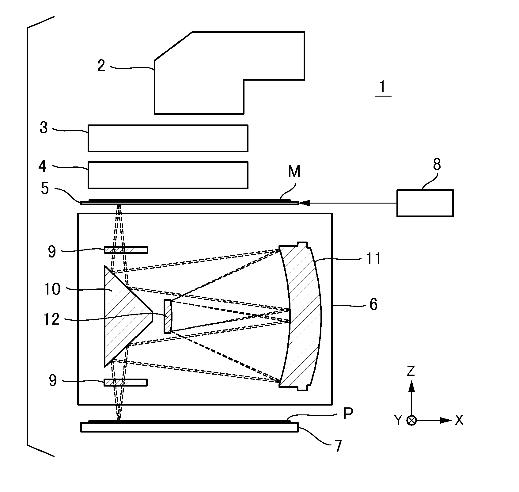
[0022]Firstly, a description will be given of an exposure apparatus according to the first embodiment of the present invention. FIG. 1 is a schematic diagram illustrating the configuration of an exposure apparatus 1 according to the present embodiment. The exposure apparatus 1 is a scanning type exposure apparatus that performs synchronous scanning of a mask (original) and a glass plate (substrate) serving as a substrate to be treated to thereby expose a pattern formed on the mask to the glass plate. Firstly, the exposure apparatus 1 includes an illumination optical system 2, an expanding optical system 3, an alignment measurement system 4, a mask stage 5 that holds a mask M on which a predetermined pattern is formed, a projection optical system 6, a substrate stage 7 that holds a glass plate P on which a photosensitive agent is applied, and a control unit 8.

[0023]The illumination optical system (illumination system) 2 has a light source (not shown) and irradiates the mask M held by...

second embodiment

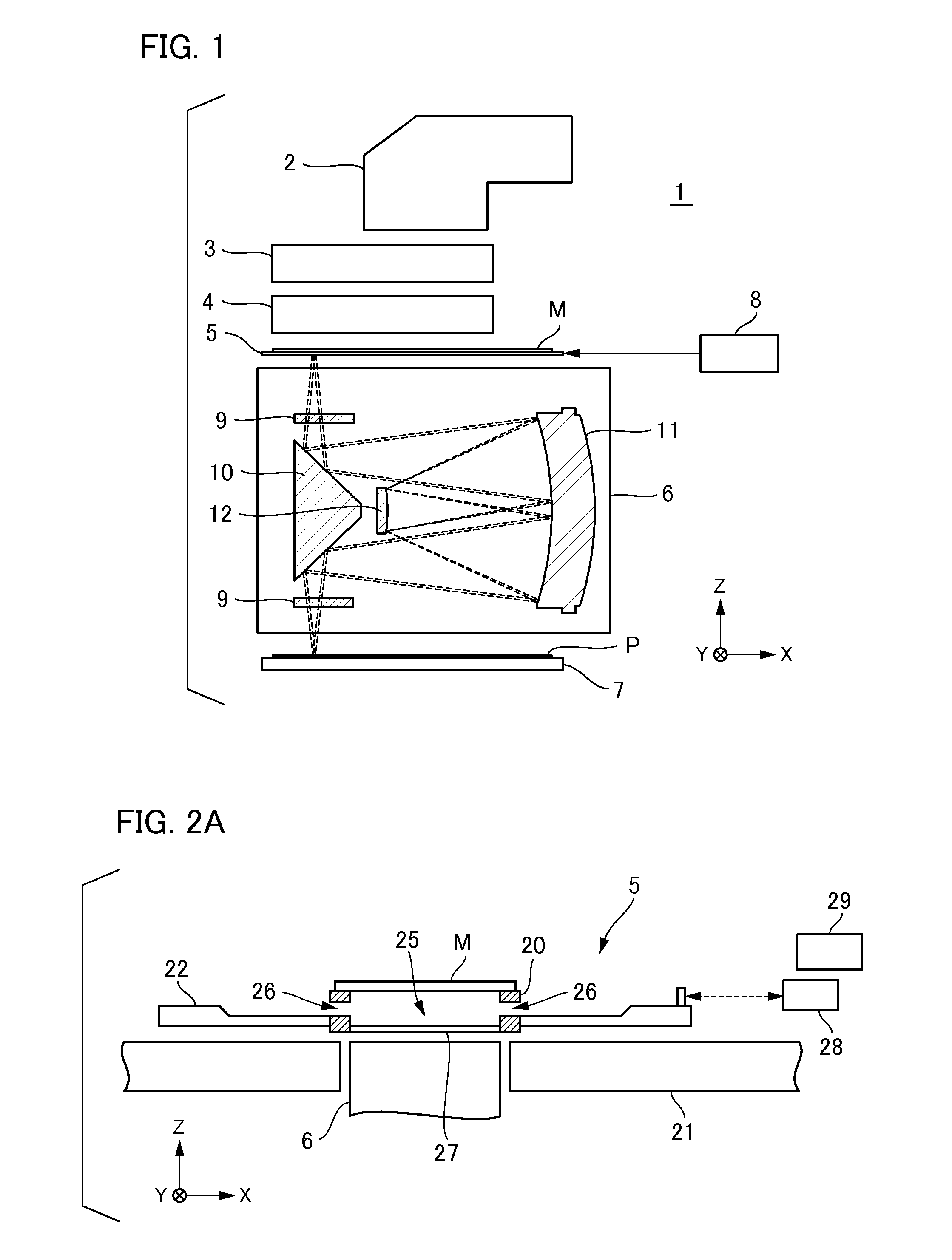
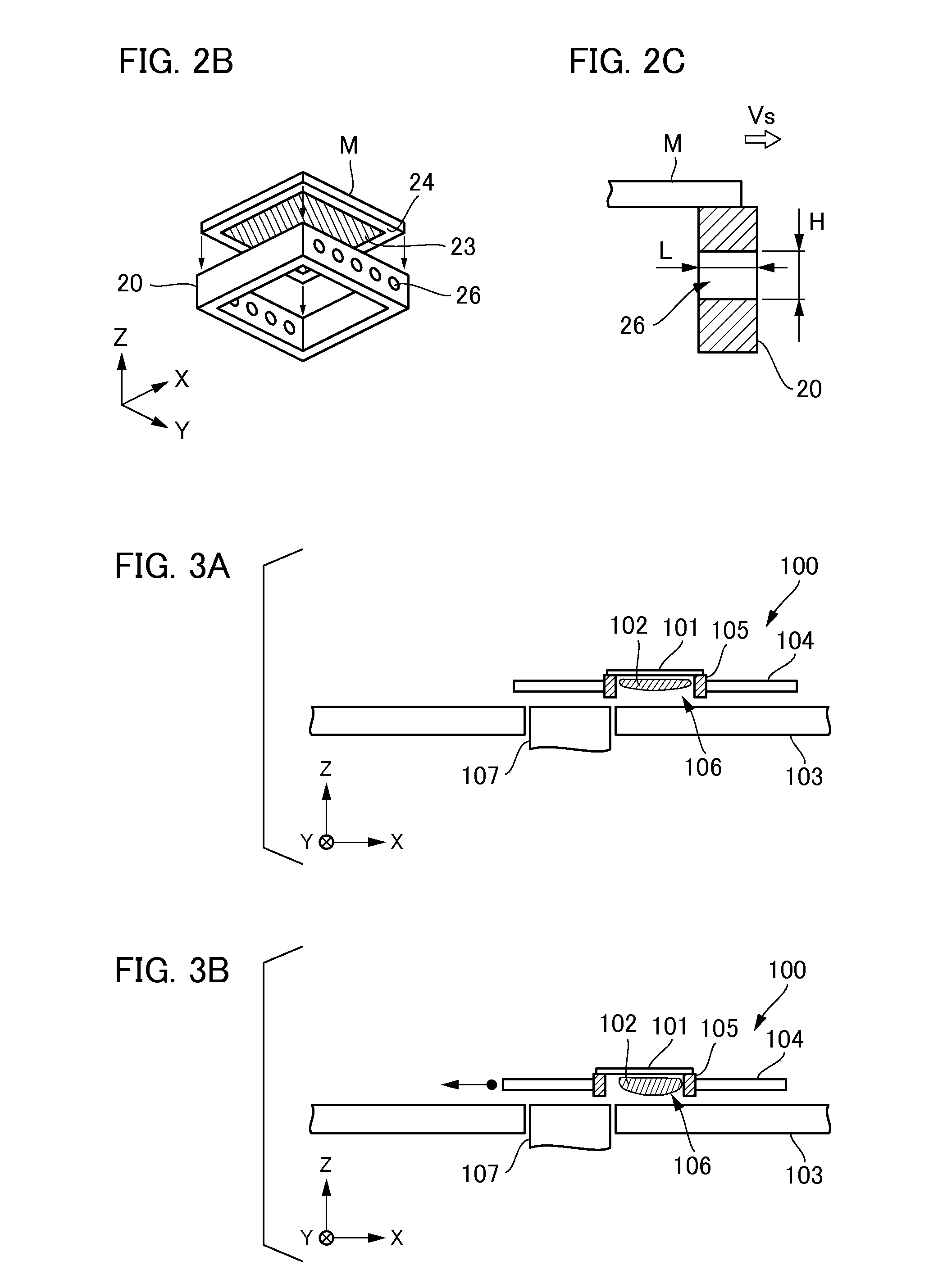
[0034]Next, a description will be given of an exposure apparatus according to the second embodiment of the present invention. Although the penetrating portion 26 is provided with the holding frame 20 for the mask stage 5 in the first embodiment described above, it is preferable that the flow of gas passing through the space 25 via the penetrating portion 26 is defined in a fixed direction in order to efficiently exhaust gas retained in the space 25 to the outside. For example, when the flow of gas is produced by the air conditioner 29 from the periphery and the side of the mask stage 5, it is preferable that gas passes through the space 25 while flowing along the main direction of gas flow produced by the air conditioner 29. Hence, in the present embodiment, two penetrating portions provided at both lateral sides of the holding frame 20 in a certain axial direction have a shape or a configuration such that the flow of gas passing through the space 25 is defined in a fixed direction....

third embodiment

[0037]Next, a description will be given of an exposure apparatus according to the third embodiment of the present invention. FIG. 5 is a schematic cross-sectional view illustrating the configuration of the mask stage 5 according to the present embodiment. In FIG. 5, the same elements as those shown in FIGS. 2A to 2C according to the first embodiment are designated by the same reference numerals and explanation thereof will be omitted. In general, the position of the mask M is determined by the fine movement positioning under the drive of the drive unit 22. Thus, it is preferable that the peripheral member of the mask M such as the holding frame 20 or the like is not affected by a mechanical load from outside as small as possible so as not to influence the fine movement positioning. Accordingly, in the present embodiment, as shown in FIG. 5, the transmitting plate 27 is supported by the drive unit 22 without being in direct contact with the holding frame 20 so that a mechanical load ...


PUM


Abstract

The exposure apparatus of the present invention has an original holding unit including a holding frame that holds an original M by attracting the outer peripheral portion thereof and a drive unit that is capable of moving the holding frame while changing an irradiation area of the light to be irradiated on a pattern. Here, the holding frame has a penetrating portion, which is capable of flowing gas which is present in a space defined by the original and the holding frame into and out from the space, provided at both front and back lateral sides of the holding frame in the direction of movement thereof, and the penetrating portion has a shape or a configuration such that the pressure loss in the flow of the gas in a first direction is less than the pressure loss in the flow of the gas in a second direction.

Description

BACKGROUND OF THE INVENTION[0001]1. Field of the Invention[0002]The present invention relates to an exposure apparatus and a device manufacturing method using the same.[0003]2. Description of the Related Art[0004]An exposure apparatus is configured to transfer a pattern of an original (reticle or mask) onto a photosensitive substrate (e.g., wafer, glass plate, and the like, where the surface thereof is coated with a resist layer) via a projection optical system in a lithography process of a manufacturing process for a semiconductor device, a liquid crystal display device, and the like. The exposure apparatus typically includes an original stage that movably holds an original. Examples of such a mechanism for holding an original onto the original stage include a mechanism utilizing a vacuum adsorption force or an electrostatic attraction force, a mechanism utilizing an actuator for generating a pressing force, or the like. In any one of these mechanisms, it is preferable that a holdi...

Claims


Application Information

Patent Timeline
Patent Type & Authority Applications(United States)
IPC IPC(8): G03B27/62
CPCG03F7/70875G03F7/707
Inventor UMEMURA, ATSUSHIHASEGAWA, NORIYASU
Owner CANON KK
Features
  • R&D
  • Intellectual Property
  • Life Sciences
  • Materials
  • Tech Scout
  • Unparalleled Data Quality
  • Higher Quality Content
  • 60% Fewer Hallucinations
Learn More