Sliding member and method of manufacturing same

a technology of sliding member and manufacturing method, which is applied in the direction of rotary machine parts, mechanical equipment, lubricant composition, etc., can solve the problems of difficult to change the sintering temperature, limited combinations of different types of base materials such as metal backings and porous sintered layer materials, etc., and achieves enhanced bonding force between base 12 and resin layer 14. , the effect of easy peeling

Inactive Publication Date: 2013-01-24
DAIDO METAL CO LTD
View PDF1 Cites 13 Cited by
  • Summary
  • Abstract
  • Description
  • Claims
  • Application Information

AI Technical Summary

Benefits of technology

[0051]In the present embodiment, the bonding force between base 12 and resin layer 14 is enhanced in the high load surface region by controlling opening area ratio x1 in the high load surface region. More specifically, opening area ratio x1 in the high load surface region is controlled to range between 0.2≦x1≦0.8. Opening area ratio x1, when represented in percentage, range between 20% ≦x1≦80%.
[0052]When opening area ratio x1 in the high load surface region is equal to or greater than 0.2, in other words, 20%, the bonding force between base 12 and resin layer 14 in the high load surface region is high, and thus, resin layer 14 does not easily peel from base 12 even when subjected to high load. Further, opening area ratio x1 in the high load surface region being equal to or less than 0.8, in other words, 80%, is advantageous in terms of manufacturability. In the low load surface region, on the other hand, large opening area ratio need not be established since it is not subjected to high load on a regular basis. Thus, the amount of machining in the low load surface region of impregnated layer 13 of slide member 11 can be reduced. In case materials with relatively high heat conductivity such as steel is used for base 12, the ratio of base 12 that occupies impregnated layer 13 is relatively increased as the opening area ratio becomes smaller which is advantageous in terms of heat dissipation.

Problems solved by technology

From a bonding perspective, the possible combinations between different types of base materials such as metal backing and different types of porous sintered layer materials are generally limited.
It is thus, for instance, difficult to change the sintering temperature.

Method used


Image

  • Sliding member and method of manufacturing same
  • Sliding member and method of manufacturing same
  • Sliding member and method of manufacturing same

Examples


Embodiment Construction

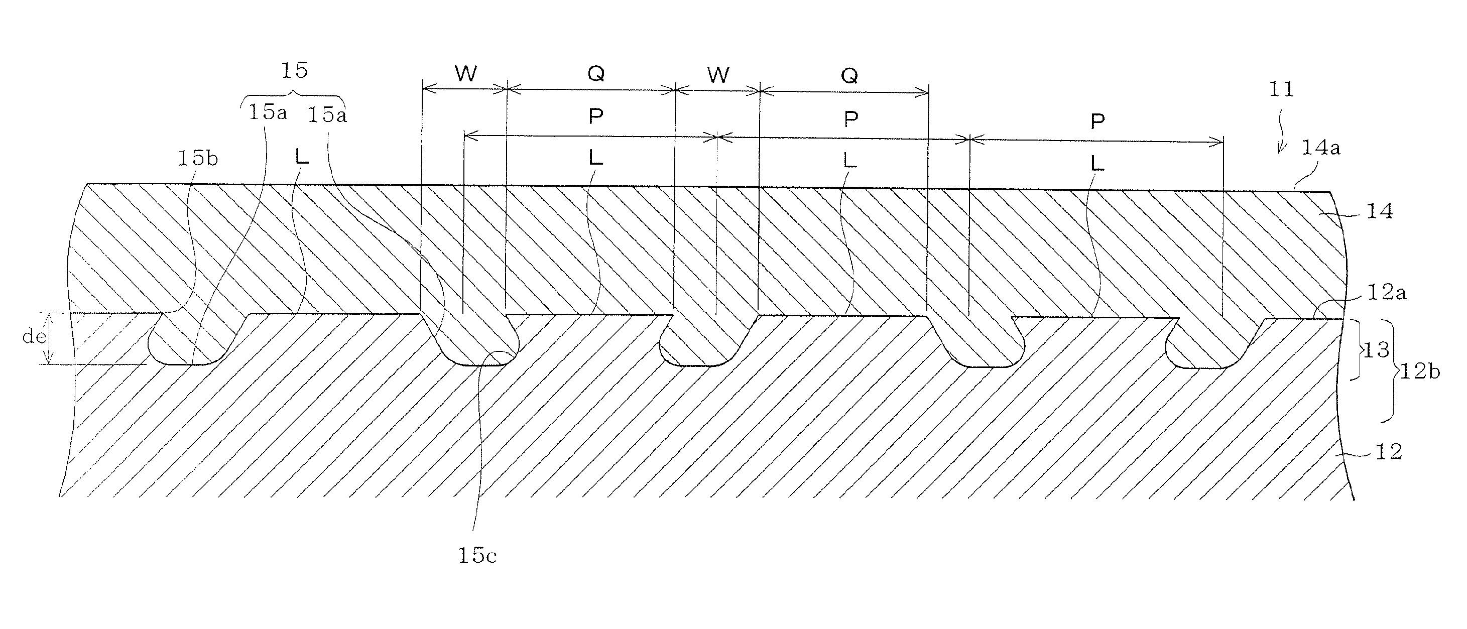
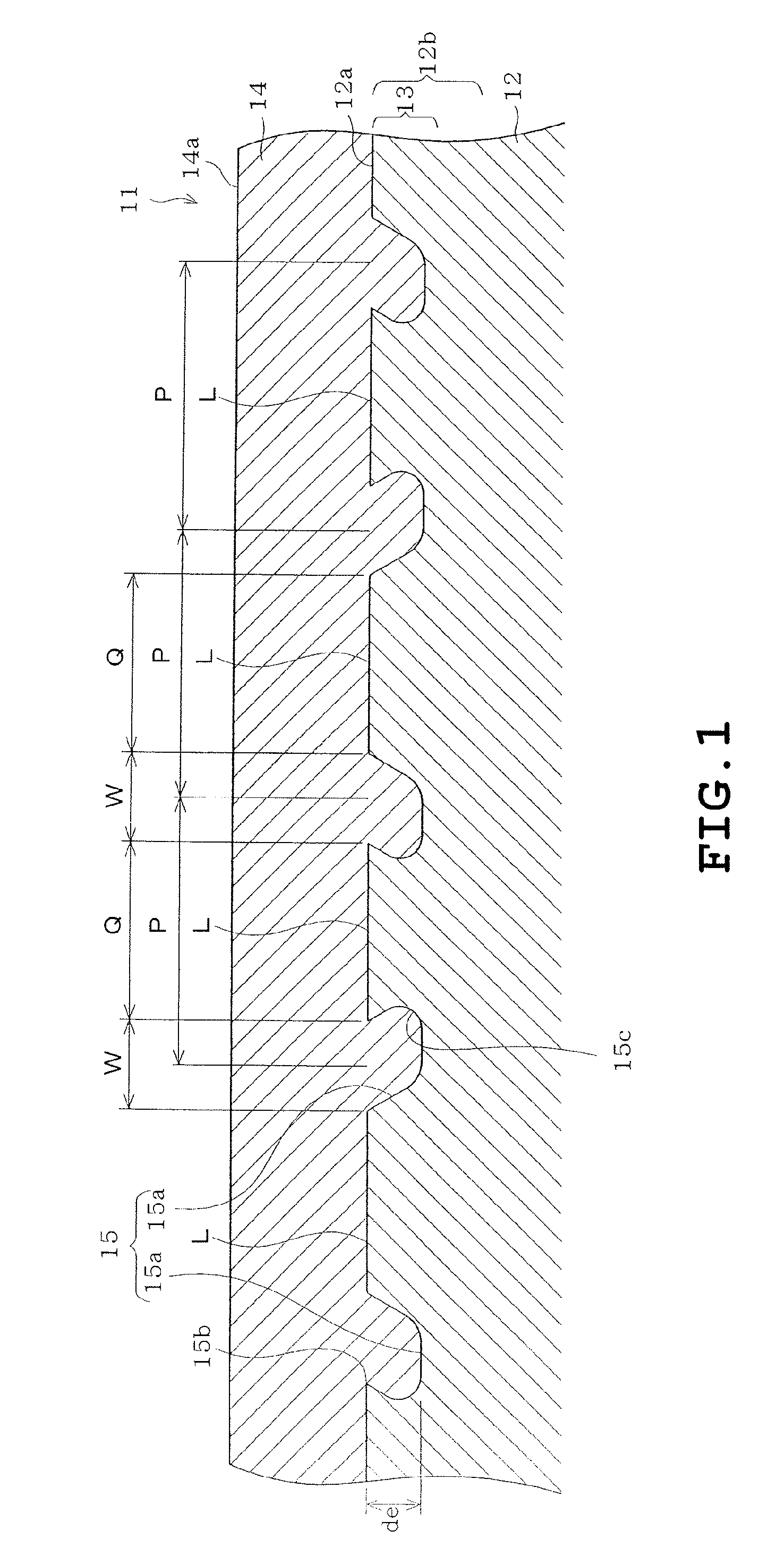
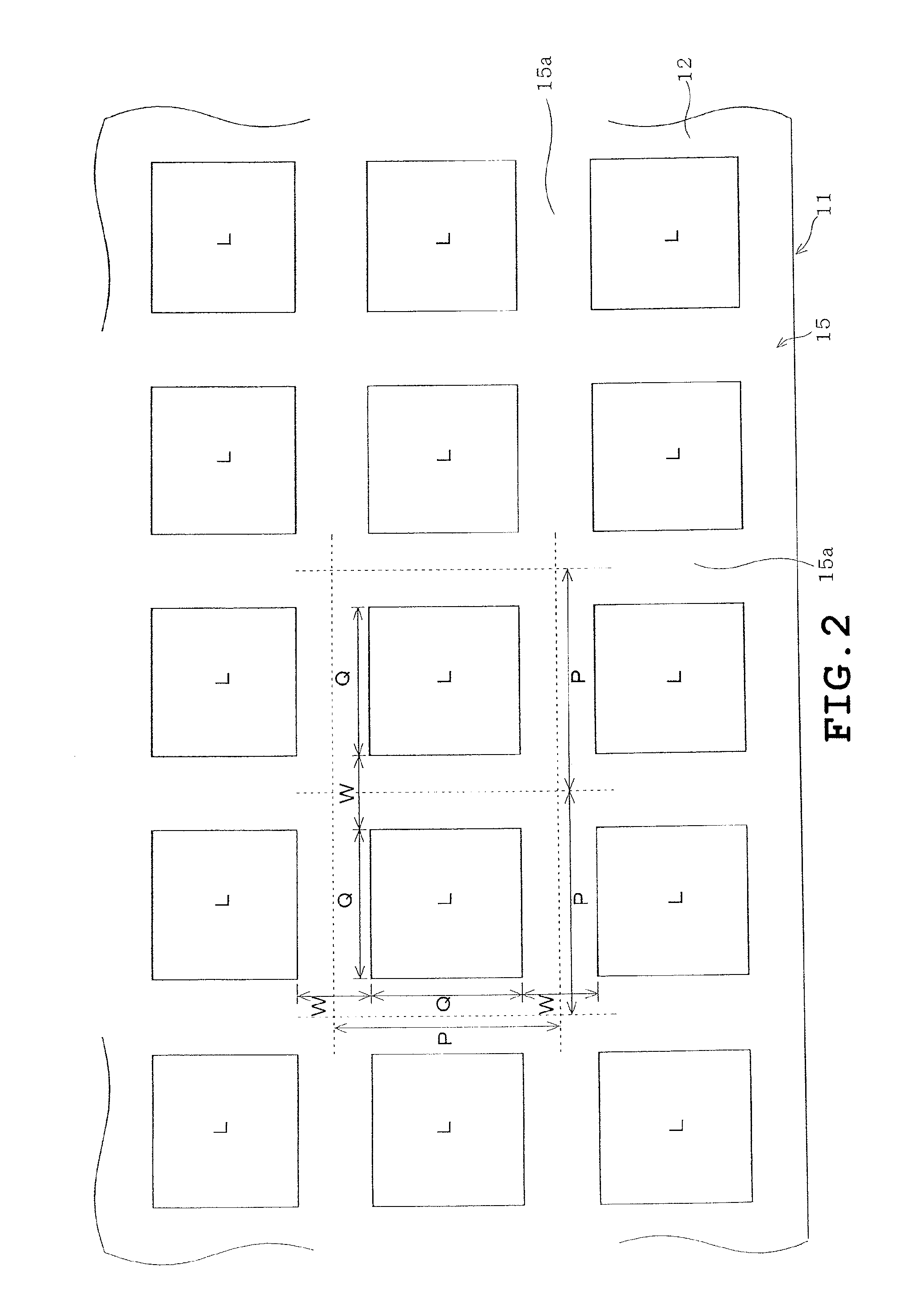
[0066]Next, an embodiment will be described with reference to FIGS. 1 to 3 and 7 and 8.

[0067]Slide member 11 of the present embodiment is obtained by preparing a base metal backing 12 made, for instance, of steel, providing impregnated layer 13 by forming recess 15 on surface portion 12b of base metal backing 12, and impregnating and covering impregnated layer 13 with resin layer 14 primarily composed of PEEK.

[0068]In order to verify the bonding force, in other words, the shearing stress of base 12 and resin layer 14 of slide member 11 of the present embodiment, EXAMPLES based on the embodiment and COMPARATIVE EXAMPLES based on conventional porous sintered configuration were prepared and were screened through a shear test.

[0069]More specifically, EXAMPLES were prepared as follows.

[0070]First, a steel backing plate serving as the base and having a thickness of 20 mm was prepared. Then, recesses were formed, by wire cut electrical discharge machining, on the surface portion of the bas...


PUM

PropertyMeasurementUnit
depthaaaaaaaaaa
surface roughnessaaaaaaaaaa
areaaaaaaaaaaa

Abstract

A slide member provided with a base, an impregnated layer, and a resin layer. The base made of metal or ceramic. The impregnated layer is defined on a surface portion of a sliding side of the base by forming a recess on the base. The resin layer impregnates the impregnated layer so as to cover a sliding side surface of the base.

Description

TECHNICAL FIELD[0001]The present invention relates to a slide member provided with a resin layer and a method of manufacturing the same.BACKGROUND[0002]Some slide members are provided with a resin layer that serves as a sliding portion. The resin layer is typically made of PEEK (Polyetheretherketon) that exhibits outstanding sliding properties such as seizure resistance, wear resistance, and mechanical strength.[0003]The resin which forms the resin layer, does not easily establish a chemical bond with metal which is a different type of material. Thus, when the resin layer is applied directly on a metal base serving as a support layer, the resin layer may easily peel from the base. Such being the case, patent document 1 teaches providing a porous sintered layer, obtained by sintering lead bronze powder, on the base and impregnating a portion of the resin layer into the porous sintered layer. Patent Document 1, i.e. JP H08-210357 A teaches that the resin layer is secured on the base t...

Claims


Application Information

Patent Timeline
Patent Type & Authority Applications(United States)
IPC IPC(8): F16C33/20B23P13/00F16C33/12
CPCF16C33/205F16C2208/00Y10T29/49995F16C2240/42F16C2206/40F16C33/20F16C2208/36F16C33/208F16C33/201C04B41/48F16C33/08C10M107/32
Inventor MATSUHISA, HIROICHIYOSHIMURA, HIROSHISHITO, MAKOTO
Owner DAIDO METAL CO LTD
Why Eureka
Try Eureka