Exhaust gas purification device

a technology of exhaust gas and purification device, which is applied in the direction of exhaust treatment electric control, electrical control, separation process, etc., can solve the problems of fuel vaporization, reduced in-line driveability, fuel vaporization, etc., and achieves the reduction of nox, the effect of improving the low temperature characteristic of exhaust gas post-processing device and improving the purification ra

Active Publication Date: 2013-01-31
ISUZU MOTORS LTD
View PDF11 Cites 7 Cited by
  • Summary
  • Abstract
  • Description
  • Claims
  • Application Information

AI Technical Summary

Benefits of technology

[0008]Furthermore, in a low exhaust gas temperature atmosphere where the exhaust gas temperature is low, the fuel (diesel oil) injected in the exhaust pipe arrives at the downstream side catalysts before reaching a state of advanced decomposition, and therefore filter clogging, in which the fuel blocks front surfaces of the catalysts, may occur. Moreover, during forcible regeneration (rich spiking) of the LNT, a NOx reduction efficiency may decrease such that HC slip deteriorates.
[0009]The present invention has been designed in consideration of these problems, and an object thereof is to provide an exhaust gas purification device with which a low temperature characteristic of an exhaust gas post-processing device can be improved, a NOx reduction and purification rate can be increased, and smoke generation can be effectively reduced by means of a simple configuration.
[0015]With the exhaust gas purification device according to the present invention, a low temperature characteristic of an exhaust gas post-processing device can be improved, a NOx reduction and purification rate can be increased, and smoke generation can be effectively reduced by means of a simple configuration.

Problems solved by technology

Hence, during acceleration, an air-fuel ratio A decreases, leading to a reduction in an in-cylinder pressure, and as a result, combustion may become unstable, causing the drivability to deteriorate due to acceleration failure or the like.
Hence, when the exhaust gas temperature increases, the adhered fuel may be vaporized, and as a result, smoke may be generated.
Furthermore, in a low exhaust gas temperature atmosphere where the exhaust gas temperature is low, the fuel (diesel oil) injected in the exhaust pipe arrives at the downstream side catalysts before reaching a state of advanced decomposition, and therefore filter clogging, in which the fuel blocks front surfaces of the catalysts, may occur.
Moreover, during forcible regeneration (rich spiking) of the LNT, a NOx reduction efficiency may decrease such that HC slip deteriorates.

Method used


Image

  • Exhaust gas purification device
  • Exhaust gas purification device
  • Exhaust gas purification device

Examples


Embodiment Construction

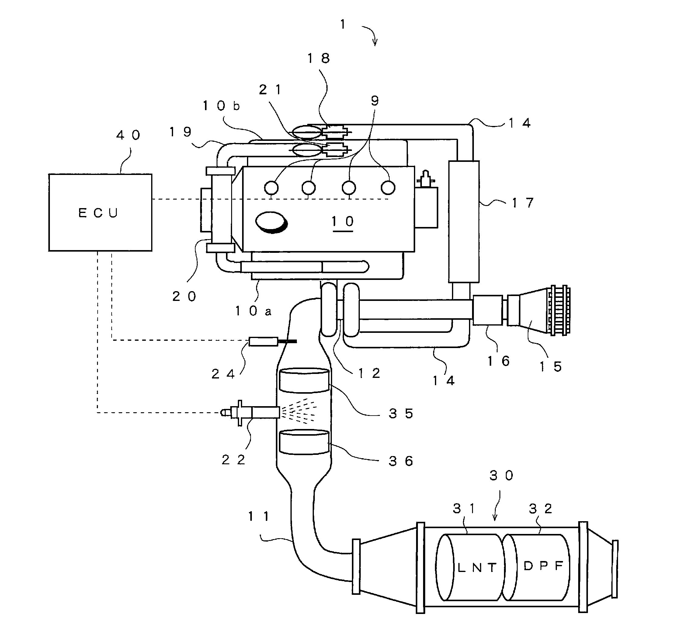
[0022]An embodiment of the present invention will be described below with reference to the drawings.

[0023]FIGS. 1 to 4 illustrate an exhaust gas purification device 1 according to this embodiment of the present invention. Identical components have been allocated identical reference numerals and have identical names and functions. Accordingly, detailed description of these components will not be repeated.

[0024]As shown in FIG. 1, a diesel engine (internal combustion engine) 10 is provided with an intake manifold 10b and an exhaust manifold 10a. Further, an intake passage 14 into which fresh air (intake air) is introduced by opening an intake value (not shown) provided in the diesel engine 10 is connected to the intake manifold 10b, and an exhaust passage 11 into which exhaust gas is discharged by opening an exhaust valve (not shown) is connected to the exhaust manifold 10a.

[0025]An intake throttle 18, an intercooler 17, a turbocharger 12, and a mass air flow sensor 16 are interposed...


PUM

PropertyMeasurementUnit
temperatureaaaaaaaaaa

Abstract

The exhaust gas purification device includes an exhaust gas post-processing device 30 provided in an exhaust passage 11 of an engine 10, an exhaust injection valve 22, a first catalyst 35, a second catalyst 36 for thermally decomposing fuel injected by the exhaust injection valve 22, an exhaust temperature estimation unit 41 for estimating an exhaust temperature, an engine injection control unit 42 for controlling fuel injection in the engine 10, and regeneration control units 43, 44 for controlling regeneration of the exhaust gas post-processing device 30. When an output value output by the exhaust gas temperature estimation unit 41 is equal to or lower than a threshold during regeneration by the regeneration control units 43, 44, the engine injection control unit 42 controls fuel injection in the engine by performing a multistage injection, which includes a post injection for supplying fuel to the first catalyst 35.

Description

CROSS REFERENCE TO RELATED APPLICATIONS[0001]This application is entitled to the benefit of and incorporates by reference essential subject matter disclosed in International Patent Application No. PCT / JP2011 / 059153 filed on Apr. 13, 2011 and Japanese Patent Application No. 2010-094342 filed on Apr. 15, 2010.TECHNICAL FIELD[0002]The present invention relates to an exhaust gas purification device that includes an exhaust gas post-processing device provided in an exhaust passage of an internal combustion engine and an in-exhaust pipe injection valve provided on an upstream side of the exhaust gas post-processing device.BACKGROUND ART[0003]A DPF (diesel particulate filter) that traps particulate matter (PM) contained in exhaust gas and an LNT (LNT occlusion reduction catalyst) that reduces and purifies NOx are used in a diesel engine (internal combustion engine) as an exhaust gas post-processing device. Further, an in-exhaust pipe injection, in which fuel is injected directly into an ex...

Claims


Application Information

Patent Timeline
Patent Type & Authority Applications(United States)
IPC IPC(8): F01N9/00F01N3/035F01N3/10
CPCB01D53/9409B01D53/944B01D53/9477B01D2251/208B01D2279/30F01N3/106F01N11/005F01N2560/06F01N2610/03F01N2900/1602F02D41/1447F02D41/405F01N2510/0684F01N3/0821F01N3/0842F01N3/2066F01N3/023F01N3/0253F01N2240/04F02D41/025Y02T10/12Y02T10/40
Inventor NAGAOKA, DAIJINAKADA, TERUO
Owner ISUZU MOTORS LTD
Why Eureka
Try Eureka