Waste to hydrogen conversion process and related apparatus

a technology of waste to hydrogen and conversion process, which is applied in the direction of cell components, sustainable manufacturing/processing, and final product manufacturing, etc., can solve the problems of high energy consumption, high cost, and inability to cleanly separate hydrogen from steam reforming process, and achieve the effect of efficient steam reduction

Inactive Publication Date: 2013-01-31
TRUSTEES OF BOSTON UNIV
View PDF3 Cites 14 Cited by
  • Summary
  • Abstract
  • Description
  • Claims
  • Application Information

AI Technical Summary

Benefits of technology

[0013]In one aspect, the invention employs an oxygen-ion-conducting solid electrolyte at elevated temperatures with a novel system of electrodes to efficiently reduce steam at the cathode to form H2-rich steam and oxidize a carbon feed containing hydrocarbons at the anode or convert hydrogen and oxygen into electrical energy.
[0017]Hydrogen will be produced at the cathode and syn-gas (mixture of CO(g) and H2(g)) may be produced at the anode depending on the nature of waste feed used; a hydrocarbon waste feed is likely to produce syn-gas. The use of the liquid metal anode allows the waste feed to be efficiently decomposed and oxidized.
[0020]In one embodiment of the invention, hydrogen can be produced from steam through electrolysis when the cost of electricity is low (e.g., at night) and electricity can be produced back from hydrogen when the cost is high. This way the device does not have to undergo any thermal cycling.

Problems solved by technology

The traditional steam reforming process does not allow clean separation of hydrogen from carbon monoxide and the other impurity oxides that are generated in the process in a single step.
This process is energy intensive and expensive but can produce clean and pure hydrogen.
This process produces pure hydrogen and syn-gas from a source of steam and hydrocarbon fuel, however, additional processing is required to obtain the syn-gas used in this process.
Clean separation of hydrogen from other gases and impurities is a complex, difficult, and expensive process.
The waste incineration process however does not produce pure hydrogen and / or syn-gas.

Method used


Image

  • Waste to hydrogen conversion process and related apparatus
  • Waste to hydrogen conversion process and related apparatus
  • Waste to hydrogen conversion process and related apparatus

Examples


Embodiment Construction

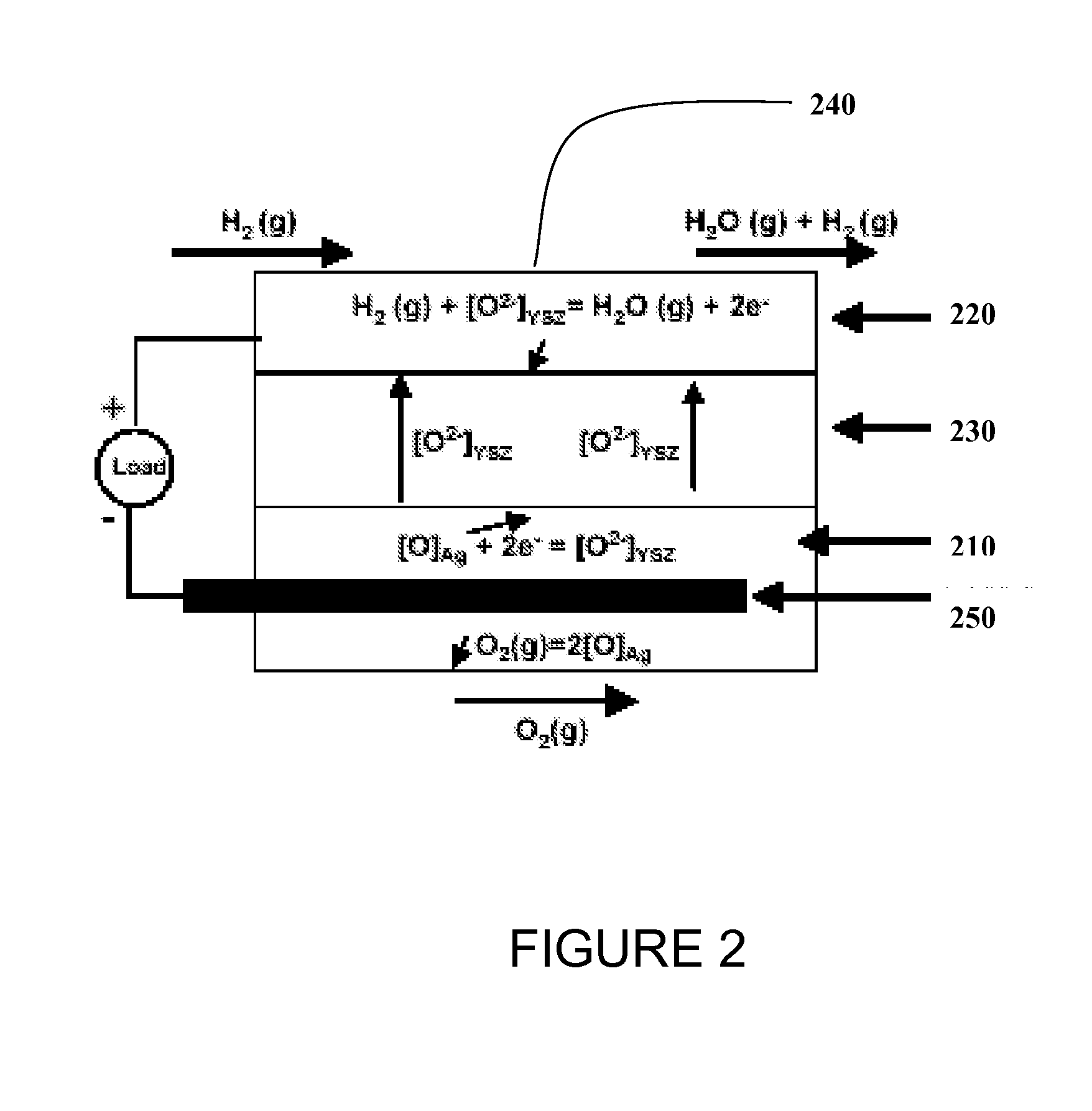
[0026]In one or more embodiments, carbon-based reversible and regenerative solid oxide fuel cell system is provided that can be operated at zero to near zero pollution emission and within environmental hazard reduction goals. The device when operated as an electrolyzer can produce hydrogen at high throughputs from steam and carbon feed and the same device can be operated in the reverse mode as a fuel cell to produce electricity from hydrogen and air / oxygen.

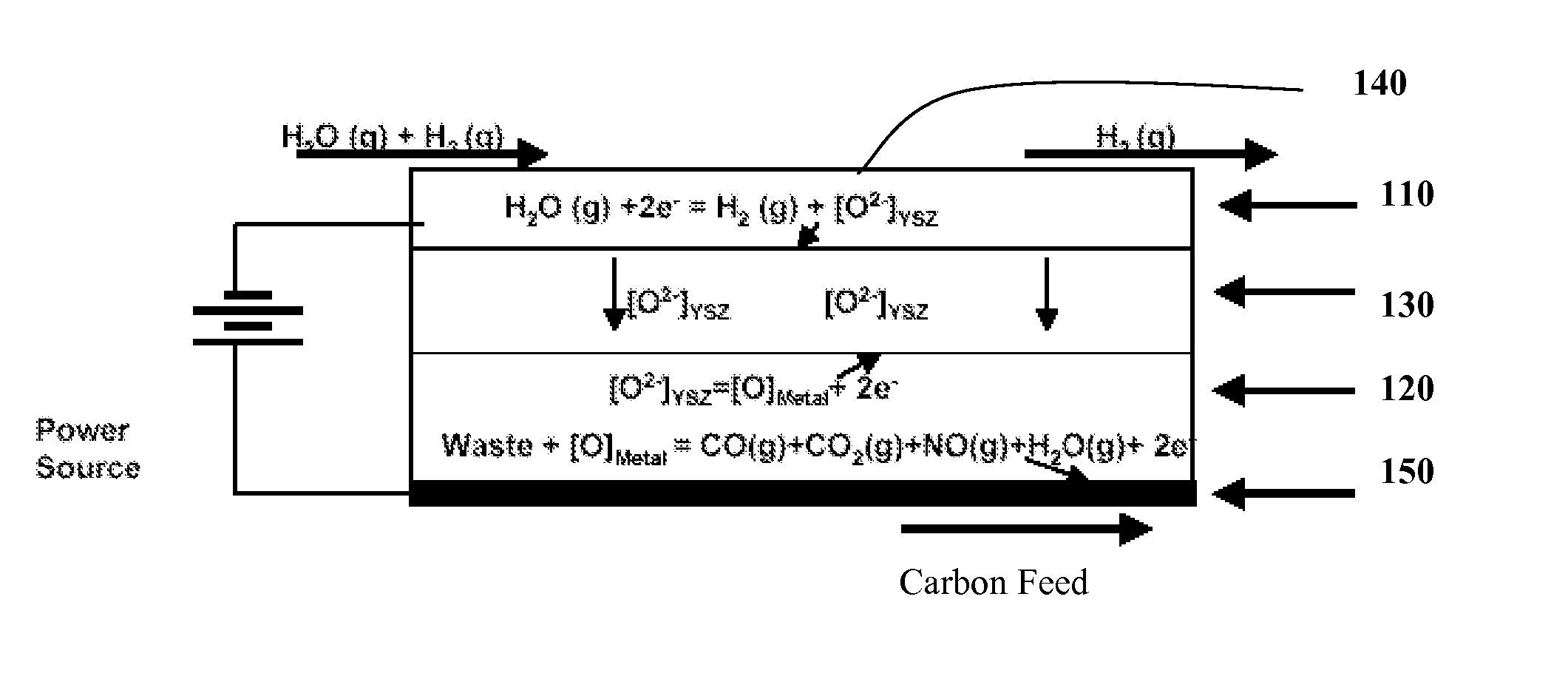
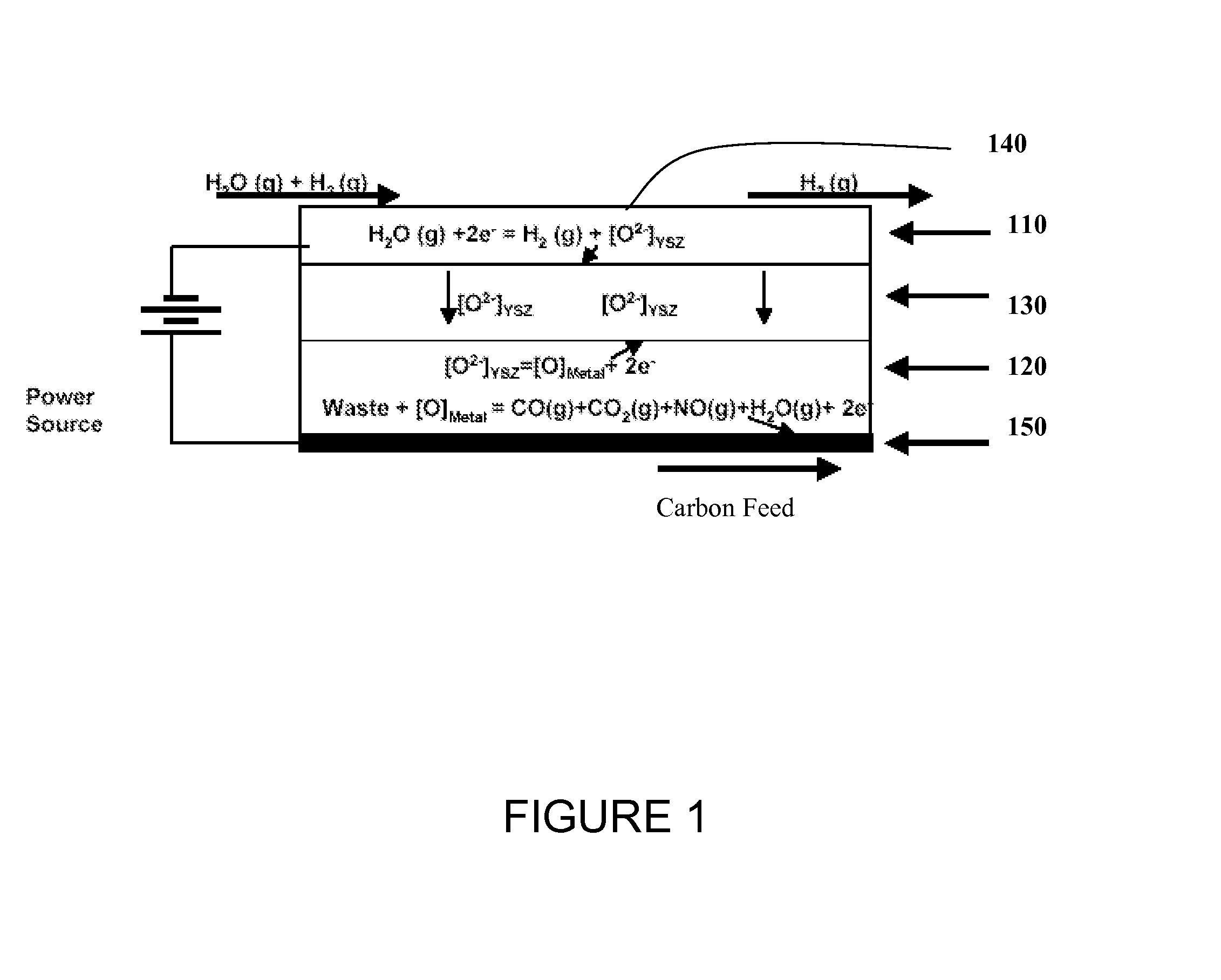
[0027]Operation of the electrochemical device for synthesizing and separating hydrogen is shown in FIG. 1. The cell is constructed with two porous electrodes that sandwich an electrolyte. The device includes a cathode 110 that is capable of stably operating at high temperatures and a liquid metal anode 120, separated by a solid oxide electrolyte 130, e.g., an oxygen ion conducting membrane. The system further includes appropriate current collectors 140, 150 for the cathode and anode, respectively. This system, operating at a tempe...


PUM

PropertyMeasurementUnit
temperaturesaaaaaaaaaa
conductiveaaaaaaaaaa

Abstract

A reversible electrochemical system includes a first electrode comprising liquid silver metal and a second electrode, said first and second electrodes separated by a oxygen ion-conducting solid electrolyte; a conduit for directing a first reactive material across the second electrode; and a conduit for contacting second reactive material with the first liquid silver electrode, wherein the cell is capable of steam electrolysis when the polarity of the electrodes is selected such that the liquid silver is an anode and the cell is capable of electrical energy generation when the polarity of the electrodes is selected such that the liquid silver is a cathode.

Description

RELATED APPLICATIONS[0001]This application is a divisional application of U.S. patent application Ser. No. 11 / 917,894, filed Oct. 21, 2008, which application is a national stage application of prior International Application No. PCT / US2006 / 023570, entitled “Waste To Hydrogen Conversion Process and Related Apparatus,” filed Jun. 16, 2006, which claims the benefit of priority to application Ser. No. 60 / 691,007, filed on Jun. 16, 2005, entitled “Solid Oxygen Fuel Cell,” the disclosure of which is incorporated herein in its entirety by reference.[0002]International Application No. PCT / US2006 / 023570 also claims the benefit of priority to application Ser. No. 60 / 760,906, filed on Jan. 20, 2006, entitled “Waste To Hydrogen Generation Using Solid Oxide Membrane Technology,” the disclosure of which is incorporated herein in its entirety by reference.BACKGROUND[0003]This invention relates to methods and systems for steam electrolysis. In particular, the invention relates to the conversion of ...

Claims


Application Information

Patent Timeline
Patent Type & Authority Applications(United States)
IPC IPC(8): C25B9/14
CPCC01B3/50C01B2203/0495C25B1/06C25B9/14H01M4/8621H01M4/90Y02E60/528H01M8/1246H01M8/186H01M2004/8684Y02E60/366Y02E60/521Y02E60/525H01M4/9041Y02E60/36Y02E60/50Y02P70/50C25B1/04C25B11/00C25B11/033
Inventor PAL, UDAY B.GOPALAN, SRIKANTH
Owner TRUSTEES OF BOSTON UNIV
Why Eureka
Try Eureka