Optical receiver, optical reception device, and correction method for optical received intensity

a technology of optical reception and optical receiver, which is applied in the direction of transmission monitoring, transmission monitoring/testing/fault-measurement systems, electrical devices, etc., can solve the problem of signal-to-noise ratio, transmission length is generally limited, and the received intensity of two optical signals may not be kept equal in some cases

Active Publication Date: 2013-01-31
NEC CORP
View PDF19 Cites 23 Cited by
  • Summary
  • Abstract
  • Description
  • Claims
  • Application Information

AI Technical Summary

Benefits of technology

[0021]According to the optical receiver of the present invention, in the optical receiver available for the RZ-DPSK modulation system, it becomes possible to correct automatically the difference in the received intensity due to the difference in the intensity or optical path of the optical signal.
[0022]Moreover, according to the coherent optical receiver of the present invention, it becomes possible to correct automatically the difference in the received intensity due to the difference in the intensity or optical path of the optical signal.

Problems solved by technology

When the transmission rate is speeded up to 40 Gbit / s and 100 Gbit / s from 10 Gbit / s, it becomes a main problem to improve the optical noise tolerance, that is, SN ratio (Signal to Noise ratio).
In other words, in the case of long-haul transmission, the transmission length is generally limited due to the optical noise arising in an optical amplifier which is used on a transmission line and in an optical transmitter and receiver.
However, the received intensity of two optical signals may not be kept equal in some cases due to the difference in the intensity or optical path between two optical signals on the path through which the optical inputting signal passes through the 1-bit delayed interferometer and lenses and then is inputted into the photodiode.
The difference in the received intensity of these signals degrades CMRR (Common Mode Rejection Ratio) and causes waveform distortion and an increase of jitter after the demodulation.
Moreover, it is difficult to control the optical received intensity mentioned above with a high degree of accuracy.
As a result, although it is necessary to use two optical receivers in order to receive one optical signal, this disadvantage can be compensated by making an amount of transmission information two times larger using polarization multiplexing scheme.

Method used


Image

  • Optical receiver, optical reception device, and correction method for optical received intensity
  • Optical receiver, optical reception device, and correction method for optical received intensity
  • Optical receiver, optical reception device, and correction method for optical received intensity

Examples


first exemplary embodiment

The First Exemplary Embodiment

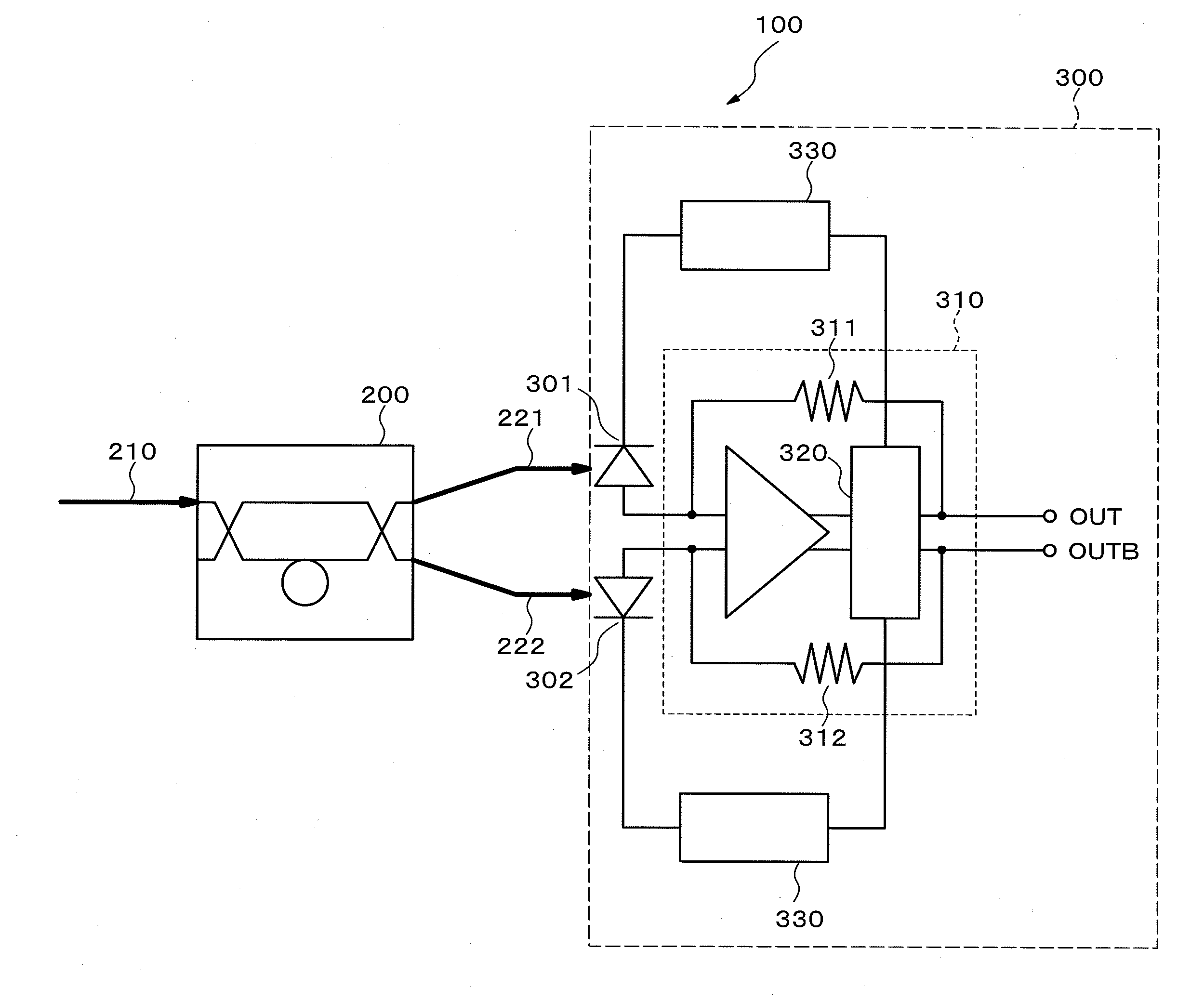
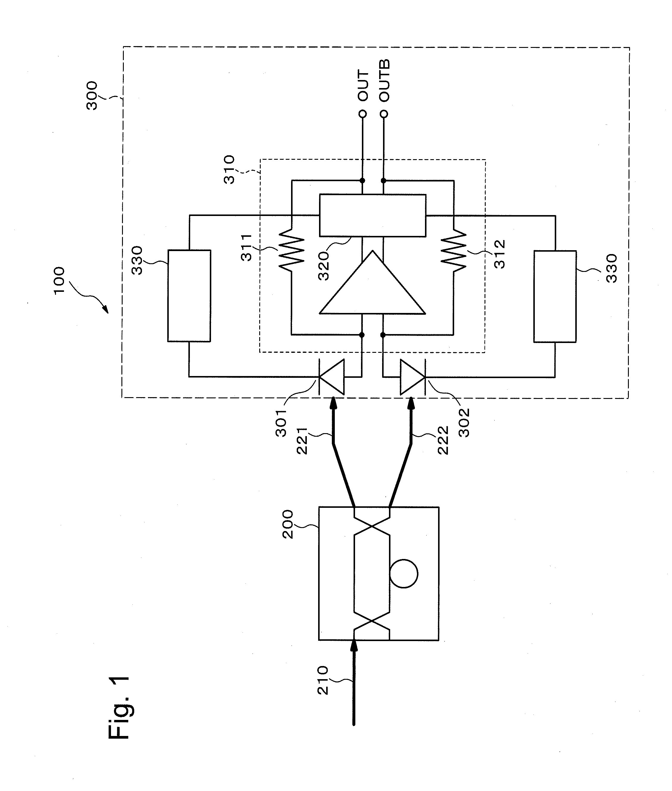
[0039]FIG. 1 is a block diagram showing the configuration of an optical reception device 100 according to the first exemplary embodiment of the present invention. The optical reception device 100 receives an optical modulated signal which is obtained by carrying out the differential phase shift keying (for example, DPSK system or DQPSK system) by using the return-to-zero (RZ) code (hereinafter, referred to as “RZ-DPSK signal”), and demodulates the received optical modulated signal. The optical reception device 100 includes a 1-bit delayed interferometer 200 and an optical receiver 300.

[0040]The 1-bit delayed interferometer 200 is provided with a 1-bit delay element in one of a pair of optical waveguides, and outputs a pair of two optical signals of a first optical signal 221 and a second optical signal 222 which correspond to a phase difference between adjacent bits of one optical input signal 210 modulated by the RZ-DPSK system. Here, it is assumed tha...

second exemplary embodiment

The Second Exemplary Embodiment

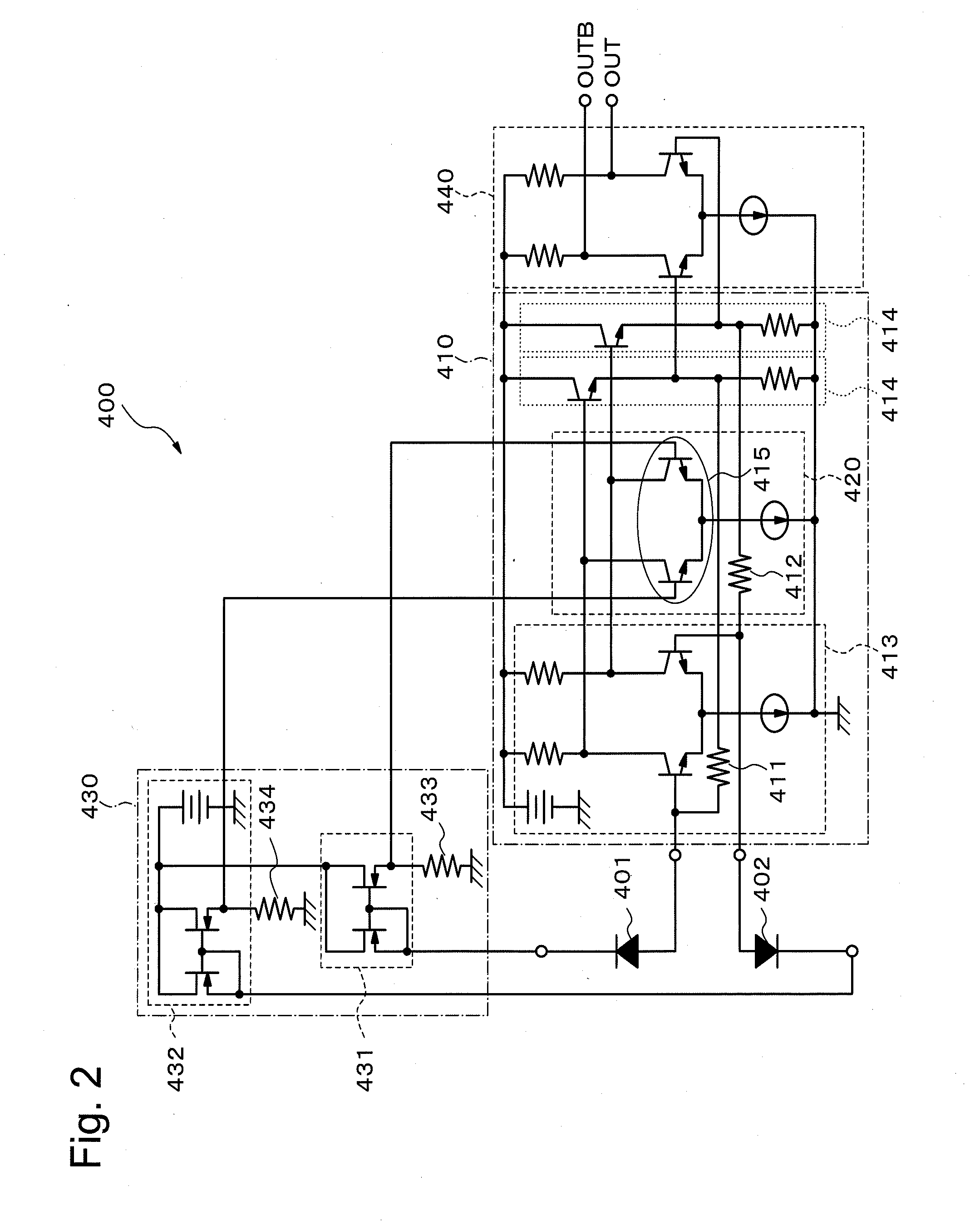
[0049]Next, the second exemplary embodiment of the present invention will be described. FIG. 2 is a circuit diagram showing the configuration of an optical receiver 400 according to the second exemplary embodiment of the present invention. The optical receiver 400 includes a first photodiode 401, a second photodiode 402, a differential transimpedance amplifier 410, a level adjustment unit 420, and a photoelectric current detection unit 430. The configuration is the same as that of the optical receiver 300 according to the first exemplary embodiment. Here, the optical receiver 400 composes an optical reception device with the 1-bit delayed interferometer 200.

[0050]The first photodiode 401 and the second photodiode 402 receive optical signals whose phase difference corresponds to the phase difference between two adjacent bits. That is to say, the first photodiode 401 receives the first optical signal with the normal phase from the first output terminal o...

third exemplary embodiment

The Third Exemplary Embodiment

[0063]Next, the third exemplary embodiment of the present invention will be described. FIG. 4 is a circuit diagram showing the configuration of an optical receiver 500 according to the third exemplary embodiment of the present invention. The optical receiver 500 includes a first photodiode 501, a second photodiode 502, a differential transimpedance amplifier 510, a level adjustment unit 520, and a photoelectric current detection unit 530. Here, the optical receiver 500 composes an optical reception device with the 1-bit delayed interferometer 200. In the optical receiver 500 according to the present exemplary embodiment, the configurations of the level adjustment unit 520 and the photoelectric current detection unit 530 are different from those of the optical receiver 400 according to the second exemplary embodiment.

[0064]The first photodiode 501 and the second photodiode 502 receive optical signals whose phase difference corresponds to the phase differ...


PUM


Abstract

In the optical receiver available for the RZ-DPSK modulation system, the difference in the received intensity due to the difference in the intensity or optical path of the optical signal cannot be corrected automatically, therefore, an optical receiver according to an exemplary aspect of the invention includes a first photodiode receiving a normal phase optical signal from a first output of a 1-bit delayed interferometer and outputting a positive signal; a second photodiode receiving a reversed phase optical signal from a second output of the 1-bit delayed interferometer and outputting a complementary signal; a differential transimpedance amplifier inputting the positive signal and the complementary signal and including a closed feedback loop for each input of the positive signal and the complementary signal; a level adjustment unit adjusting a signal level in the closed feedback loop; a photoelectric current detection unit detecting a photoelectric current generated in each of the first photodiode and the second photodiode; and wherein the level adjustment unit adjusts the signal level on the basis of an output of the photoelectric current detection unit.

Description

TECHNICAL FIELD[0001]The present invention relates to optical receivers, optical reception devices, and correction methods for optical received intensity, and in particular, to an optical receiver, an optical reception device, and a correction method for optical received intensity which are available for DPSK (Differential Phase Shift Keying) system or DQPSK (Differential Quadrature Phase Shift Keying) system using the RZ (Return-to-Zero) code as a modulation code.[0002]Moreover, the present invention relates to coherent optical receivers, and in particular, to a coherent optical receiver which is available for QPSK (Quadrature Phase Shift Keying) system as a modulation code.BACKGROUND ART[0003]The long-haul optical transmission system realizes economical and large-volume information transmission by applying the WDM (Wavelength Division Multiplexing) transmission technology which multiplexes a plurality of optical signals with various wavelengths and transmits them through one optic...

Claims


Application Information

Patent Timeline
Patent Type & Authority Applications(United States)
IPC IPC(8): H04B10/06H04B10/08H04B10/69
CPCH04B10/6931
Inventor SUZUKI, YASUYUKI
Owner NEC CORP
Why Eureka
Try Eureka