Electronic Control Unit

Inactive Publication Date: 2013-02-07
HITACHI AUTOMOTIVE SYST LTD
View PDF7 Cites 28 Cited by
  • Summary
  • Abstract
  • Description
  • Claims
  • Application Information

AI Technical Summary

Benefits of technology

[0004]In the construction described above, if the upper cover, lower cover, etc., has a large range of variation in the actual size, the thermally conductive sheet may be excessively compressed between the projecting section of the upper cover and the circuit board, to cause a large amount of local bending deformation of the circuit board, and thereby adversely affect the durability of the circuit board, and/or cause large stresses on the heating elements, and thereby adversely affect the life of soldering of terminals.
[0005]In view of the foregoing, it is desirable to provide an electronic control unit in which no such large stress is applied to a circuit board and heating elements.
[0006]According to one aspect of the present invention, an electronic control unit comprises: a casing; a circuit board housed in and fixed to the casing, wherein a heating element is mounted on the circuit board; and a thermally conductive member arranged between the casing and the heating element for thermal conduction between the casing and the heating element; wherein: the casing includes an internal surface including a contact section in intimate contact with the thermally conductive member, wherein the contact section includes a projec

Problems solved by technology

In the construction described above, if the upper cover, lower cover, etc., has a large range of variation in the actual size, the thermally conductive sheet may be excessively compressed between the projecting section of the upper cover and the circuit board

Method used


Image

  • Electronic Control Unit
  • Electronic Control Unit
  • Electronic Control Unit

Examples


first embodiment

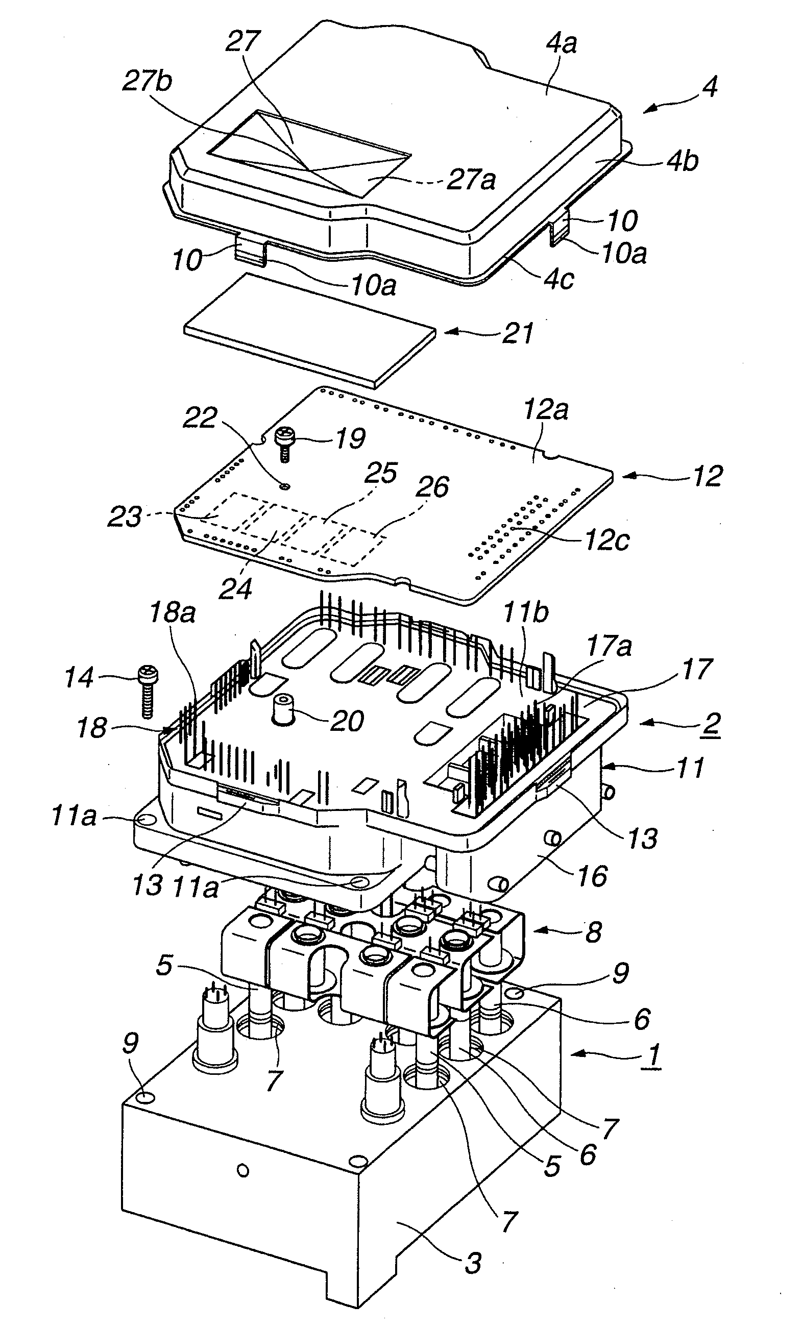
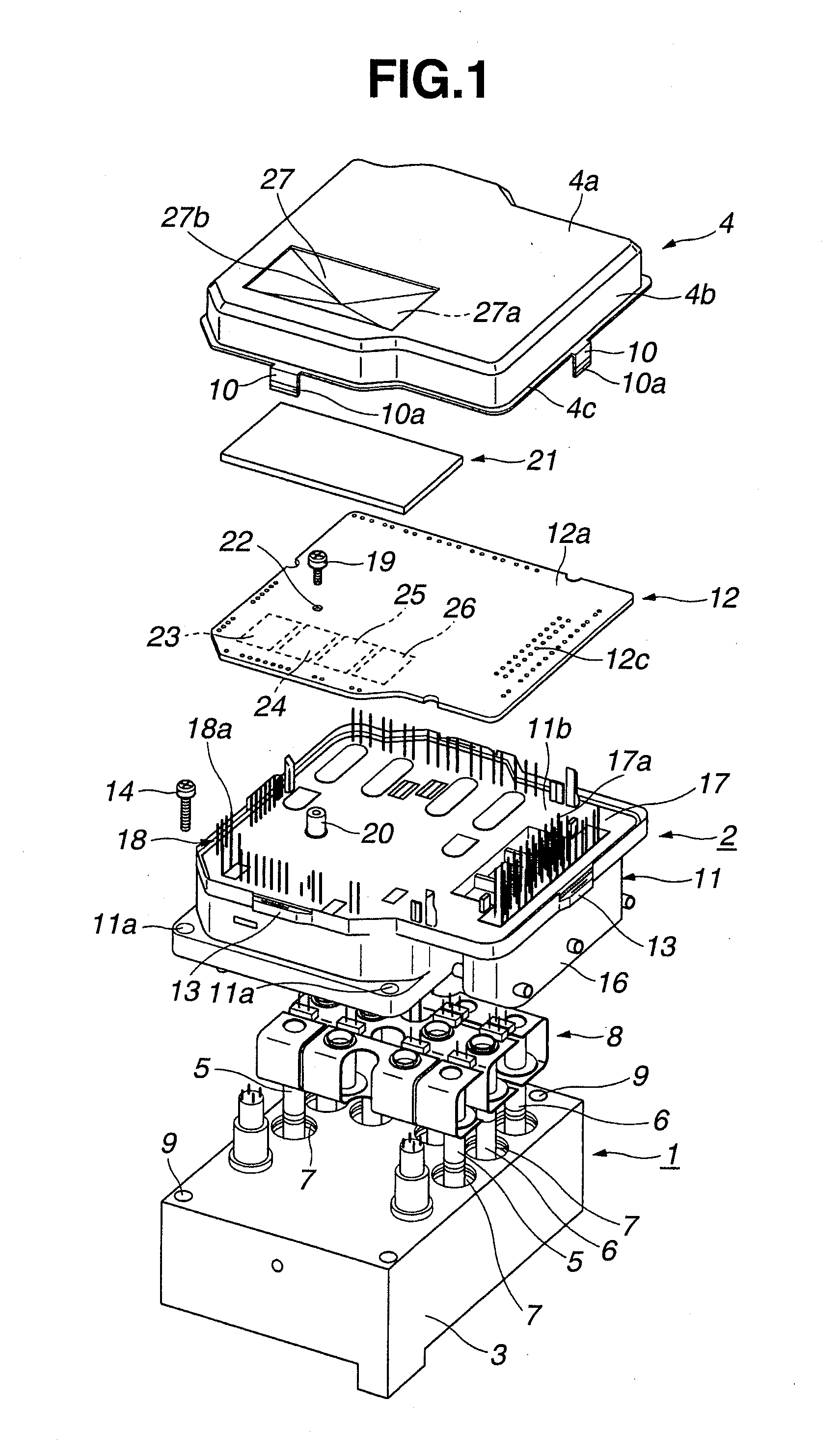
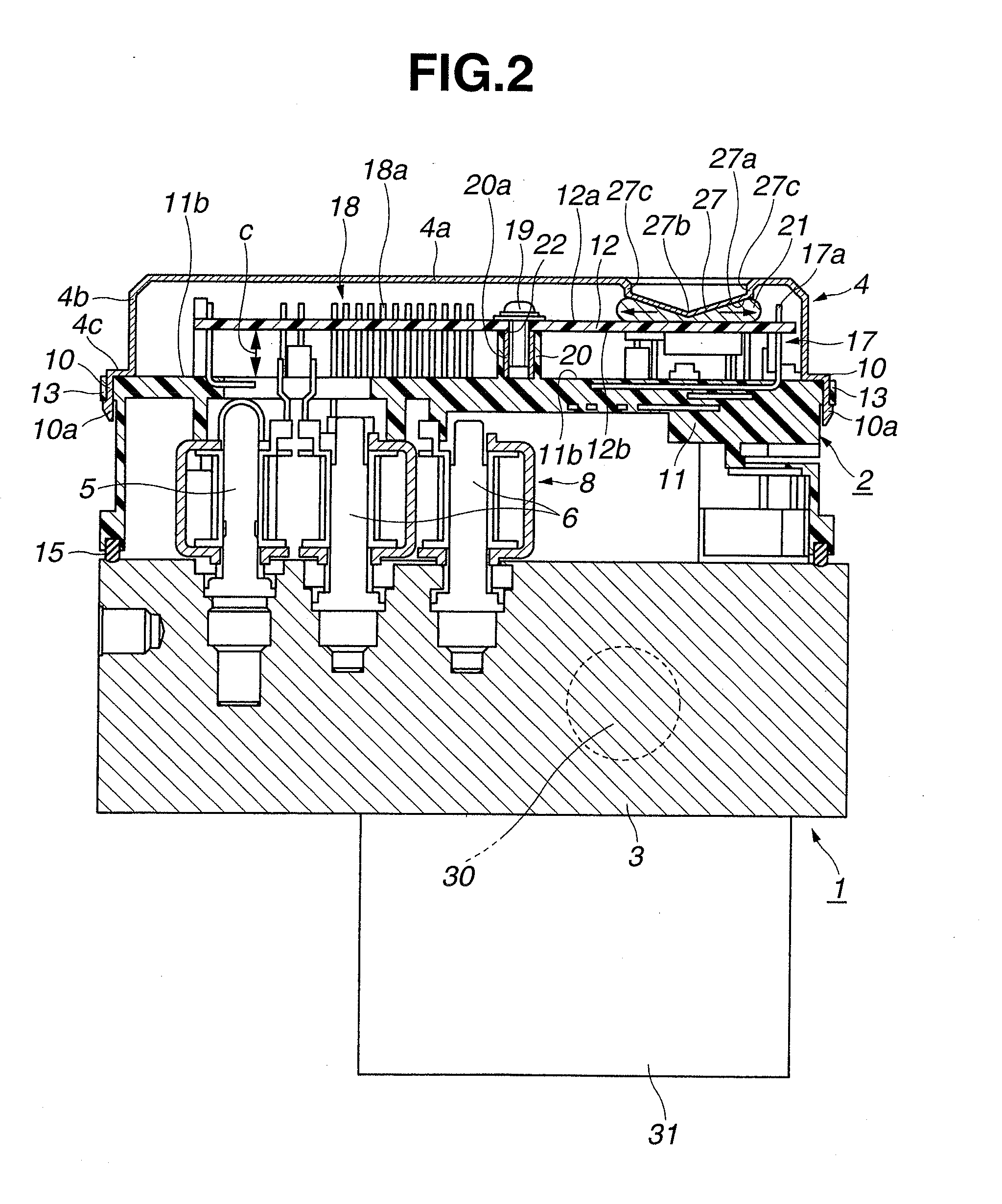
[0015]As shown in FIGS. 1 and 2, the anti-lock brake system includes a master cylinder not shown, a main passage not shown, pressure-increasing valves 5, pressure-reducing valves 6, a plunger pump 30, and a reservoir tank not shown. The master cylinder is configured to generate brake pressure depending on the amount of depression of a brake pedal. The main passage communicates the master cylinder to wheel cylinders of left and right front wheels and left and right rear wheels. Each valve 5, 6 is an electromagnetic valve provided in the main passage, which constitutes a fluid pressure control mechanism for controlling the brake pressure supplied from the master cylinder to the wheel cylinders. Each pressure-increasing valve 5 is a normally open solenoid valve, whereas each pressure-reducing valve 6 is a normally closed solenoid valve. Plunger pump 30 is provided in the main passage, and configured to pressurize and discharge brake fluid supplied to the wheel cylinders. The reservoir ...

second embodiment

[0059]FIGS. 5 and 6 show an electronic control unit according to a second embodiment of the present invention. In this embodiment, semiconductor switch elements 23, 24, 25, 26 are mounted on the lower surface 12b of printed circuit board 12, and arranged in a row at substantially even intervals. On the other hand, cover 4 is formed with two projecting sections 27. Each projecting section 27 has a pyramid shape, so that projecting sections 27 have a wave form (W-shape) cross section taken along a vertical plane as shown in FIG. 6. Namely, the lower surfaces 27a of each projecting section 27 are inclined as followed laterally from a projecting portion 27b at the center of projecting section 27. Each projecting portion 27b is located at a clearance S between semiconductor switch elements 23 and 24 or between semiconductor switch elements 25 and 26. Preferably, each projecting portion 27b is located at the center of clearance S between semiconductor switch elements 23 and 24 or between ...

third embodiment

[0063]FIGS. 7A and 7B show an electronic control unit according to a third embodiment of the present invention. In this embodiment, the arrangement of semiconductor switch elements 23, 24, 25, 26 on the lower surface 12b of printed circuit board 12 is the same as in the first embodiment. In particular, a spring member 28 is provided separately from cover 4, wherein spring member 28 is elastically deformable.

[0064]Specifically, spring member 28 is made of a thermally conductive metal sheet, and formed by press forming into a rectangular shape extending longitudinally of thermally conductive sheet 21. Spring member 28 includes a top portion 28a, a pair of leg portions 28b, 28b, and a pair of contact portions 28c. Top portion 28a is substantially flat. Each leg portion 28b extends downward from one end of top portion 28a. Contact portion 28c is connected between top portion 28a and leg portion 28b, and is adapted to be in intimate contact with the upper surface of thermally conductive ...


PUM


Abstract

An electronic control unit includes a casing, a circuit board, and a thermally conductive member. The circuit board is housed in and fixed to the casing. A heating element is mounted on the circuit board. The thermally conductive member is arranged between the casing and heating element for thermal conduction therebetween. The casing includes an internal surface including a contact section in intimate contact with the thermally conductive member. The contact section includes a projecting portion projecting toward the thermally conductive member. The projecting portion is located out of an area of the circuit board, wherein the heating element is located in the area. The heating element is mounted on one side of the circuit board. The thermally conductive member is fixed to another side of the circuit board, and located to face the heating element via the circuit board.

Description

BACKGROUND OF THE INVENTION[0001]The present invention relates to an electronic control unit applicable to a vehicle anti-lock brake system, etc.[0002]Japanese Patent Application Publication No. 2008-193108 discloses an electronic control unit for a motor vehicle. This electronic control unit includes: a casing made of aluminum alloy and having an upper cover and a lower cover; and a printed circuit board housed in the casing and arranged between the upper cover and the lower cover. The printed circuit board is provided with electrical parts constituting a control circuit, wherein the electrical parts are mounted on an upper side of the printed circuit board. The electrical parts include heating elements such as semiconductor switches and power ICs for driving actuators such as an electric motor and a solenoid.[0003]The upper cover of the casing includes a projecting section projecting toward the printed circuit board. For cooling the heating elements, a thermally conductive sheet i...

Claims


Application Information

Patent Timeline
IPC IPC(8): H05K7/20
CPCB60T7/042B60T8/368H05K7/20454H05K7/2049H01L2924/0002H05K7/20854H01L2924/00
Inventor NAGASHIMA, KAZUAKITAKAGI, RYOTAKANEKO, SUSUMU
Owner HITACHI AUTOMOTIVE SYST LTD
Why Eureka
Try Eureka