Twist drill for advanced materials

a technology of advanced materials and drill bits, which is applied in the direction of drill bits, manufacturing tools, wood boring tools, etc., can solve the problems of difficult control of the drilling process, increased risk of hand drilling, and difficulty in producing uniform holes, so as to improve the quality of the hole. , the effect of good hole quality

Active Publication Date: 2013-02-14
SANDVIK INTELLECTUAL PROPERTY AB
View PDF17 Cites 14 Cited by
  • Summary
  • Abstract
  • Description
  • Claims
  • Application Information

AI Technical Summary

Benefits of technology

[0230]In respect of the fourth proposal, the present inventors have identified a combination of features that assist in providing good hole quality, particularly when drilling composite materials as described herein, especially for automated drilling.
[0231]In particular, the present inventors have found that the provision of a flute having both a linear section where the helix angle does not vary, and a variable section where the helix angle changes can improve hole quality, particularly exit hole quality, especially for composite materials such as CFRP and the like.

Problems solved by technology

Fibre-containing composite materials such as CFRP and GFRP represent a particular challenge, especially in terms of good hole quality.
Furthermore, in the aerospace industry especially, these materials are often drilled by hand, rather than by automated drilling because the workpiece (e.g. component or panel) may not be accessible to the arm of an automated drilling apparatus.
Hence, hand drilling brings with it the difficulty of producing uniform holes: different users may apply different levels of force to the workpiece and so hole quality can vary.
Hand drilling is also more susceptible to the problem of “pushing” or “pull through”, whereby a drill can exert an axial force on the user at particular points during drilling of a hole.
This makes it difficult for the user to control the drilling process and can lead to reduced hole uniformity and hole quality.
However, these are unable to provide a variable level of thrust force and good exit hole quality.

Method used


Image

  • Twist drill for advanced materials
  • Twist drill for advanced materials
  • Twist drill for advanced materials

Examples


Embodiment Construction

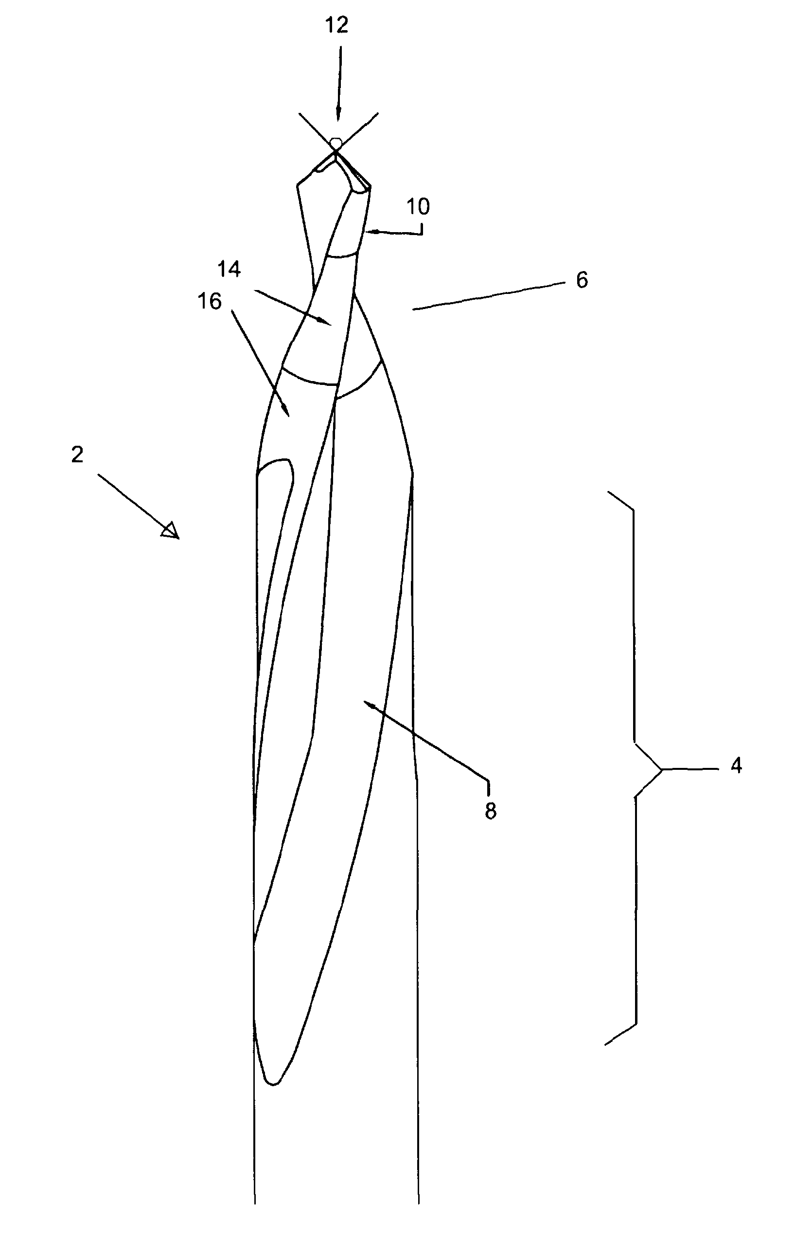
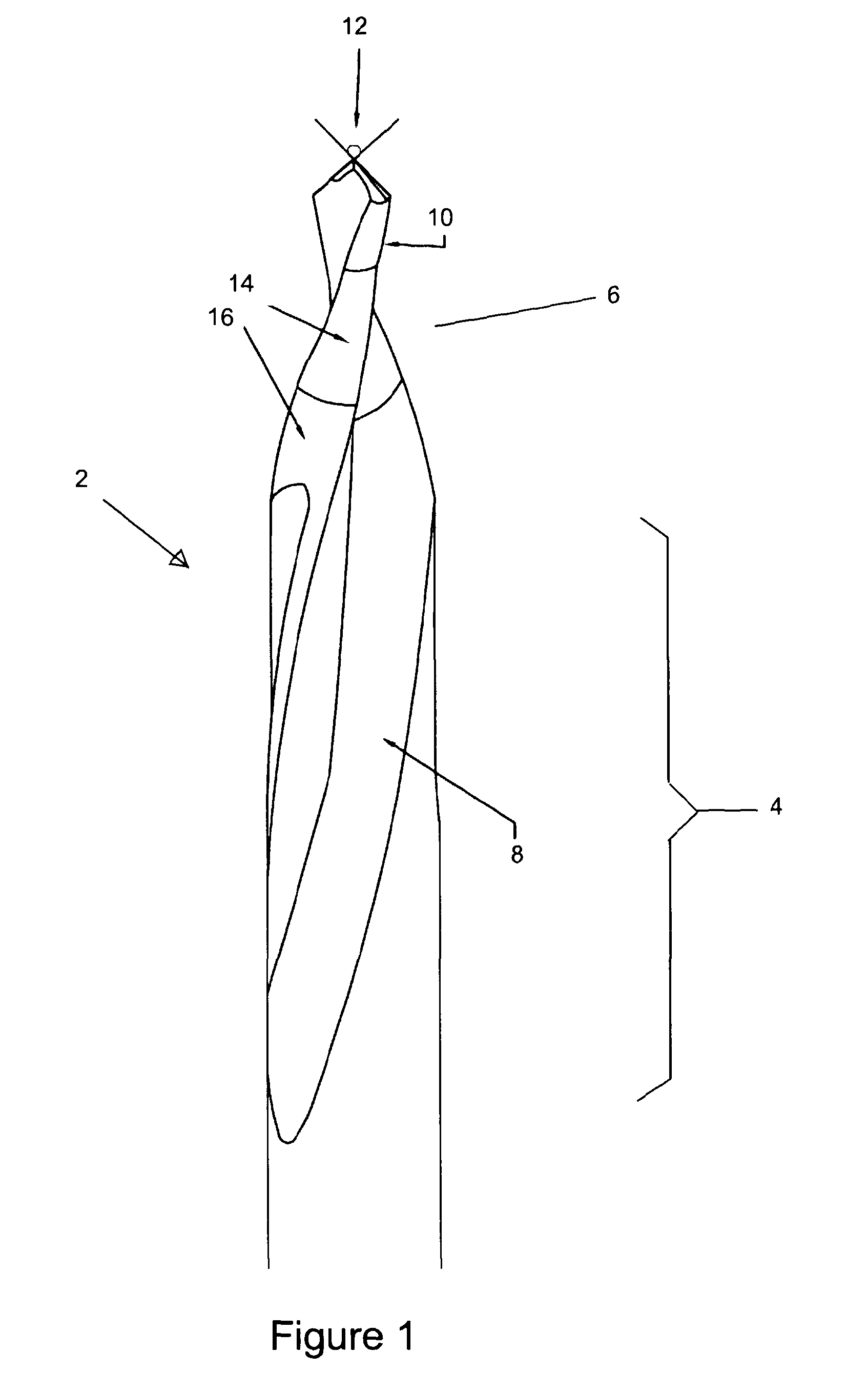
[0284]FIG. 1 shows a twist drill 2 of the present invention. The drill comprises a shank (not shown), drill body 4 and drill tip 6. Two helical flutes 8 extend from the drill tip to the drill body. The helix angle is comparatively large at the start of the helix, being 50° and comparatively small at the end of the helix, being 10°. Other angles are possible, for example 25° to 60°, suitably 40° to 60°, for the start angle, and 0° to 35° for the finish angle.

[0285]The helix is formed using a spline function. The spline function is selected so that the change in helix angle as a function of the axial distance from the start of the helix at the drill tip is smooth and continuous. This is in contrast to conventional variable helix drills wherein the change in helix angle is stepped, such that there are transitions or steps between helix angles. In contrast, this embodiment, with its smooth and continuous variation in helix angle does not have any such steps. This has the significant adv...


PUM

PropertyMeasurementUnit
relief angleaaaaaaaaaa
helix angleaaaaaaaaaa

Abstract

The present invention is concerned with twist drills for drilling of composite materials such as carbon fibre reinforced plastic (CFRP) and glass fibre reinforced plastic (GFRP). The present invention proposes that a twist drill (2) is provided with a variable helix having a defined start and finish helix angle, in combination with primary and secondary relief angles such that the drill (2) is adapted to minimise thrust force, particularly when used for drilling fibre—containing composite materials and especially for hand drilling. Start and finish helix angles of 50° and 10°; 50° and 30°; and 30° and 10° have been shown to provide excellent cutting performance and exit hole quality. A large secondary chisel edge angle (24) has also been found to contribute to excellent performance with composite materials, including stack machining.

Description

TECHNICAL FIELD OF THE INVENTION[0001]The present invention relates to twist drills and in particular twist drills adapted for drilling, especially hand drilling, of composite materials such as carbon fibre reinforced plastic (CFRP) or glass fibre reinforced plastic (GFRP).BACKGROUND[0002]Fibre-containing composite materials such as CFRP and GFRP represent a particular challenge, especially in terms of good hole quality. Furthermore, in the aerospace industry especially, these materials are often drilled by hand, rather than by automated drilling because the workpiece (e.g. component or panel) may not be accessible to the arm of an automated drilling apparatus.[0003]Unlike automated drilling where the drilling is computer controlled (i.e. drill speed and drill feed rate), hand drilling requires the user to control the speed and feed. Thus, whilst damage to the workpiece (e.g. composite material) can be moderated in the case of automated drilling by control of drill speed and feed ra...

Claims


Application Information

Patent Timeline
Patent Type & Authority Applications(United States)
IPC IPC(8): B23B51/02B23B35/00
CPCB23B51/02B23B2226/27B23B2226/36B23B2251/046Y10T408/906B23B2251/18B23B2251/606Y10T408/03Y10T408/9097B23B2251/14
Inventor GOH, WAN TSINLIMB, JOHN ROBERT
Owner SANDVIK INTELLECTUAL PROPERTY AB
Why Eureka
Try Eureka